
Physics for Scientists and Engineers: Foundations and Connections
1st Edition
ISBN: 9781133939146
Author: Katz, Debora M.
Publisher: Cengage Learning
expand_more
expand_more
format_list_bulleted
Videos
Textbook Question
Chapter 33, Problem 12PQ
At one instant, a current of 6.0 A flows through part of a circuit as shown in Figure P33.12. Determine the instantaneous potential difference between points A and B if the current starts to decrease at a constant rate of 1.0 × 10² A/s.
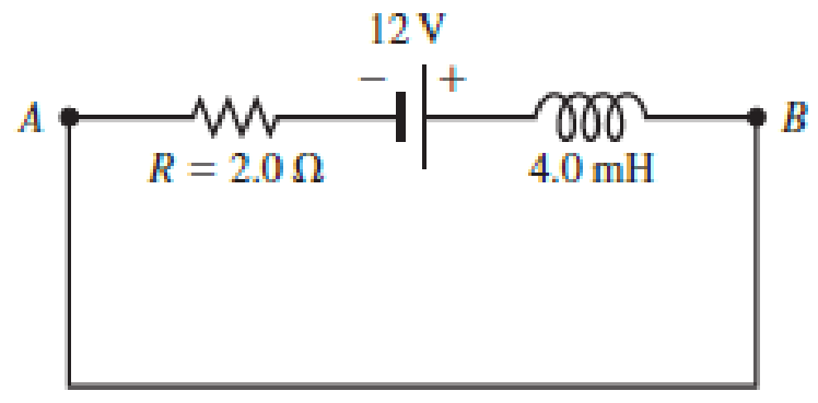
FIGURE P33.12
Expert Solution & Answer

Trending nowThis is a popular solution!

Students have asked these similar questions
Chapter 32, Problem 018
Your answer is partially correct. Try again.
The circuit in the figure consists of switch S, a 4.50 V ideal battery, a 35.0 M2 resistor, and an airfilled capacitor. The capacitor has
parallel circular plates of radius 5.10 cm, separated by 1.50 mm. At time t = 0, switch S is closed to begin charging the capacitor. The
electric field between the plates is uniform. At t = 160 µs, what is the magnitude of the magnetic field within the capacitor, at radial
distance 3.30 cm?
C
S
R
Number
Units
T.
Use correct number of significant digits; the tolerance is +/-1 in the 3rd significant digit
Chapter 32, Problem 018
Your answer is partially correct. Try again.
The circuit in the figure consists of switch S, a 4.50 V ideal battery, a 35.0 M2 resistor, and an airfilled capacitor. The capacitor has
parallel circular plates of radius 5.10 cm, separated by 1.50 mm. At time t = 0, switch S is closed to begin charging the capacitor. The
electric field between the plates is uniform. At t = 160 µs, what is the magnitude of the magnetic field within the capacitor, at radial
distance 3.30 cm?
S
R
Number
Units
Use correct number of significant digits; the tolerance is +/-1 in the 3rd significant digit
There is a current of 0.25 A in the circuit of Figure P23.69.a. What is the direction of the current? Explain.b. What is the value of the resistance R?c. What is the power dissipated by R?d. Make a graph of potential versus position, starting from V = 0 V in the lower left corner and proceeding clockwise.See Figure P23.9 for an example.
Chapter 33 Solutions
Physics for Scientists and Engineers: Foundations and Connections
Ch. 33.1 - Prob. 33.1CECh. 33.1 - Prob. 33.2CECh. 33.2 - Prob. 33.3CECh. 33.3 - Prob. 33.4CECh. 33.4 - Prob. 33.5CECh. 33.5 - Prob. 33.6CECh. 33.7 - Prob. 33.7CECh. 33 - Prob. 1PQCh. 33 - Prob. 2PQCh. 33 - Prob. 3PQ
Ch. 33 - Prob. 4PQCh. 33 - Prob. 5PQCh. 33 - Prob. 6PQCh. 33 - Prob. 7PQCh. 33 - Prob. 8PQCh. 33 - Prob. 9PQCh. 33 - Prob. 10PQCh. 33 - Prob. 11PQCh. 33 - At one instant, a current of 6.0 A flows through...Ch. 33 - Prob. 13PQCh. 33 - Prob. 14PQCh. 33 - Prob. 15PQCh. 33 - In Figure 33.9A (page 1052), the switch is closed...Ch. 33 - Prob. 17PQCh. 33 - Prob. 18PQCh. 33 - Prob. 19PQCh. 33 - Prob. 20PQCh. 33 - Prob. 21PQCh. 33 - Prob. 22PQCh. 33 - In the LC circuit in Figure 33.11, the inductance...Ch. 33 - A 2.0-F capacitor is charged to a potential...Ch. 33 - Prob. 26PQCh. 33 - Prob. 27PQCh. 33 - Prob. 28PQCh. 33 - For an LC circuit, show that the total energy...Ch. 33 - Prob. 30PQCh. 33 - Prob. 31PQCh. 33 - Prob. 32PQCh. 33 - Prob. 33PQCh. 33 - Suppose you connect a small lightbulb across a DC...Ch. 33 - Prob. 35PQCh. 33 - Prob. 36PQCh. 33 - Prob. 37PQCh. 33 - Prob. 38PQCh. 33 - Prob. 39PQCh. 33 - Prob. 40PQCh. 33 - Prob. 41PQCh. 33 - Prob. 42PQCh. 33 - Prob. 43PQCh. 33 - In an ideal AC circuit with capacitance, there is...Ch. 33 - Prob. 45PQCh. 33 - Prob. 46PQCh. 33 - Prob. 47PQCh. 33 - Prob. 48PQCh. 33 - Prob. 49PQCh. 33 - An AC generator with an rms emf of 15.0 V is...Ch. 33 - Prob. 51PQCh. 33 - Prob. 52PQCh. 33 - Prob. 53PQCh. 33 - Prob. 54PQCh. 33 - Prob. 55PQCh. 33 - Prob. 56PQCh. 33 - Prob. 57PQCh. 33 - Prob. 58PQCh. 33 - Prob. 59PQCh. 33 - An AC source of angular frequency is connected to...Ch. 33 - An RLC series circuit is constructed with R =...Ch. 33 - Prob. 62PQCh. 33 - A series RLC circuit driven by a source with an...Ch. 33 - Prob. 64PQCh. 33 - Prob. 65PQCh. 33 - Prob. 66PQCh. 33 - Prob. 67PQCh. 33 - Prob. 68PQCh. 33 - Prob. 69PQCh. 33 - Prob. 70PQCh. 33 - Problems 71 and 72 paired. Figure P33.71 shows a...Ch. 33 - Prob. 72PQCh. 33 - Prob. 73PQCh. 33 - Prob. 74PQCh. 33 - Prob. 75PQCh. 33 - In a series RLC circuit with a maximum current of...Ch. 33 - Prob. 77PQCh. 33 - Two coaxial cables of length with radii a and b...Ch. 33 - Prob. 79PQCh. 33 - Prob. 80PQCh. 33 - Prob. 81PQCh. 33 - Prob. 82PQCh. 33 - Prob. 83PQCh. 33 - Prob. 84PQ
Knowledge Booster


Learn more about
Need a deep-dive on the concept behind this application? Look no further. Learn more about this topic, physics and related others by exploring similar questions and additional content below.Similar questions
- (a) What is the average power output of a heart defibrillator that dissipates 400 J of energy in 10.0 ms? (b) Considering the high-power output, why doesn’t the defibrillator produce serious bums?arrow_forwardIn the circuit of Figure P27.25, the switch S has been open for a long time. It is then suddenly closed. Take = 10.0 V, R1 = 50.0 k, R2 = 100 k, and C = 10.0 F. Determine the time constant (a) before the switch is closed and (b) after the switch is closed. (c) Let the switch be closed at t = 0. Determine the current in the switch as a function of time. Figure P27.25 Problems 25 and 26.arrow_forwardIn the circuit of Figure P27.25, the switch S has been open for a long time. It is then suddenly closed. Determine the time constant (a) before the switch is closed and (b) after the switch is closed. (c) Let the switch be closed at t = 0. Determine the current in the switch as a function of time. Figure P27.25 Problems 25 and 26.arrow_forward
- The circuit shown in Figure P28.78 is set up in the laboratory to measure an unknown capacitance C in series with a resistance R = 10.0 M powered by a battery whose emf is 6.19 V. The data given in the table are the measured voltages across the capacitor as a function of lime, where t = 0 represents the instant at which the switch is thrown to position b. (a) Construct a graph of In (/v) versus I and perform a linear least-squares fit to the data, (b) From the slope of your graph, obtain a value for the time constant of the circuit and a value for the capacitance. v(V) t(s) In (/v) 6.19 0 5.56 4.87 4.93 11.1 4.34 19.4 3.72 30.8 3.09 46.6 2.47 67.3 1.83 102.2arrow_forwardA parallel plate capacitor, circular in shape, is connected to a ℰ = 9.6 V battery and a R = 2100 Ω resistor in series as shown in the figure. The radius of each of the circular plate is a = 0.95 m and they are separated by a gap of d = 0.16 m. a) What is the current, in amperes, from the battery when the switch is closed at t=0? b) What is the magnetic field, in T, at a distance of r= 1.2m from the axis of the capacitor when the switch is closed?arrow_forwarda. What are the magnitude and direction of the current in the 18 Ω resistor in Figure P23.7?b. Draw a graph of the potential as a function of the distance traveled through the circuit, traveling clockwise from V = 0 V at the lower left corner. See Figure P23.9 for an example of such a graph.arrow_forward
- 1. The switch has been in position a for a long time. It is switched to position b at t = 0.0 s 9.0 V a b 27 2.0 μF 50 Ω a. What is the charge Q on the capacitor immediately after the switch is changed? b. What is the current I through the resistor immediately after the switch is changed? c. What is the charge Q on the capacitor at t = 50 μs? d. What is the current I through the resistor at t = 50 µs?arrow_forwardCopper has a resistivity of ρc = 1.72 × 10⁻⁸ Ω⋅m. An extension cord made of copper is connected to a DC electric motor which requires a current of at least Imin = 4.5 A in order to operate. The cord is connected to a V = 151 V source. A. Input an expression for the maximum ratio of length to cross-sectional area, γ, the cord can have if the motor is to operate. B. What is the ratio numerically in 1/m? C. Experimentally, it is found that the maximum length the cord can be is Lmax = 30 m. What is the wire's minimum diameter, Dmin, in meters?arrow_forwardIn The circuit given in Figure A, the current passed through the resistance 1 is į=2A and the resistance are R1=2.00 Q, R=3.00 2, R3=2.50 2, R=6.0 2, R=4.00 2 and Re=3.50 2. a) What is the equivalent resistance of the circuit? b) What is the emf of the battery? R1 R, R5 R3 R4 Figure A|arrow_forward
- In the figure ɛ1 = 6.88 V, ɛ2 = 12.7 V, R1 = 96.3 Q, R2 = 180 Q, and R3 = 318 Q. One point of the circuit is grounded (V = 0). What are the (a) size and (b) direction (up or down) of the current through resistance 1, the (c) size and (d) direction (left or right) of the current through resistance 2, and the (e) size and (f) direction of the current through resistance 3? (g) What is the electric potential at point A? R2arrow_forwardUseful Constants: k = 9.00 × 10º Nm² C2 8.85 x 10⁻¹² C² Nm2 %3D e = 1.6 x 10⁻¹⁹ C me = 9.11 x 10 mp = 1.67 × 10⁻²⁷kg %3D -27 mn = 1.68 x 10 %3Darrow_forwardYou connect a battery, resistor, and capacitor as in (Figure 1), where R = 14.0 Ω and C = 3.00 ×10^-6 F. The switch S is closed at t = 0. When the current in the circuit has magnitude 3.00 A, the charge on the capacitor is 40.0 × 10^−6 C. At what time t after the switch is closed is the charge on the capacitor equal to 40.0 x 10^-6 C? When the current has magnitude 3.00 A, at what rate is energy being stored in the capacitor?arrow_forward
arrow_back_ios
SEE MORE QUESTIONS
arrow_forward_ios
Recommended textbooks for you
 Physics for Scientists and Engineers: Foundations...PhysicsISBN:9781133939146Author:Katz, Debora M.Publisher:Cengage Learning
 Physics for Scientists and Engineers with Modern ...PhysicsISBN:9781337553292Author:Raymond A. Serway, John W. JewettPublisher:Cengage Learning
 Physics for Scientists and EngineersPhysicsISBN:9781337553278Author:Raymond A. Serway, John W. JewettPublisher:Cengage Learning
 Principles of Physics: A Calculus-Based TextPhysicsISBN:9781133104261Author:Raymond A. Serway, John W. JewettPublisher:Cengage Learning
 Physics for Scientists and Engineers, Technology ...PhysicsISBN:9781305116399Author:Raymond A. Serway, John W. JewettPublisher:Cengage Learning
Physics for Scientists and Engineers: Foundations...
Physics
ISBN:9781133939146
Author:Katz, Debora M.
Publisher:Cengage Learning
Physics for Scientists and Engineers with Modern ...
Physics
ISBN:9781337553292
Author:Raymond A. Serway, John W. Jewett
Publisher:Cengage Learning
Physics for Scientists and Engineers
Physics
ISBN:9781337553278
Author:Raymond A. Serway, John W. Jewett
Publisher:Cengage Learning
Principles of Physics: A Calculus-Based Text
Physics
ISBN:9781133104261
Author:Raymond A. Serway, John W. Jewett
Publisher:Cengage Learning
Physics for Scientists and Engineers, Technology ...
Physics
ISBN:9781305116399
Author:Raymond A. Serway, John W. Jewett
Publisher:Cengage Learning
What is Electromagnetic Induction? | Faraday's Laws and Lenz Law | iKen | iKen Edu | iKen App; Author: Iken Edu;https://www.youtube.com/watch?v=3HyORmBip-w;License: Standard YouTube License, CC-BY