1 Introductory Concepts 2 Number Systems, Operations, And Codes 3 Logic Gates 4 Boolean Algebra And Logic simplification 5 Combinational Logic Analysis 6 Functions Of Combinational Logic 7 Latches, Flip-flops, And Timers 8 Shift Registers 9 Counters 10 Programmable Logic 11 Data Storage 12 Signal Conversion And Processing 13 Data Transmission 14 Data Processing And Control expand_more
3.1 The Inverter 3.2 The And Gate 3.3 The Or Gate 3.4 The Nand Gate 3.5 The Nor Gate 3.6 The Exclusive-or And Exclusive-nor Gates 3.7 Programmable Logic 3.8 Fixed-function Logic Gates 3.9 Troubleshooting Chapter Questions expand_more
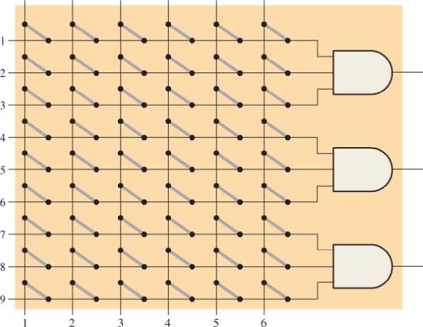
Problem 1TFQ: An inverter performs the NOR operation. Problem 2TFQ: An AND gate can have only two inputs Problem 3TFQ: If any input to an OR is 1, the output is 1. Problem 4TFQ: If all inputs to an AND gate are 1, the output is 0. Problem 5TFQ: A NAND gate has an output that is opposite the output of an AND gate Problem 6TFQ: A NOR gate can be considered as an OR gate followed by an inverter. Problem 7TFQ: The output of an exclusive-OR is 0 if the inputs are opposite. Problem 8TFQ Problem 9TFQ: Once programmed, PLD logic can be changed. Problem 10TFQ: Fan-out is the number of similar gates that a given gate can drive. Problem 1ST: When the input to an inverter is HIGH (1), the output is HIGH or 1 LOW or 1 HIGH or 0 LOW or 0 Problem 2ST: An inverter performs an operation known as complementation assertion inversion both answers (a) and... Problem 3ST: The output of an AND gate with inputs A, B, and C is a 1 (HIGH) when A=1,B=1,C=1 A=1,B=0,C=1... Problem 4ST: The output of an OR gate with inputs A, B, and C is a 1 (HIGH) when... Problem 5ST: A pulse is applied to each input of a 2-input NAND gate. One pulse goes HIGH at t = 0 and goes back... Problem 6ST: A pulse is applied to each input of a 2-input NOR gate. One pulse goes HIGH at t = 0 and goes back... Problem 7ST: A pulse is applied to each input of an exclusive-OR gate. One pulse goes HIGH at t = 0 and goes back... Problem 8ST Problem 9ST: The purpose of a programmable link in an AND array is to connect an input variable to a gate input... Problem 10ST: The term OTP means open test point one-time programmable output test program output terminal... Problem 11ST Problem 12ST Problem 13ST: Two ways to enter a logic design using PLD development software are text and numeric text and... Problem 14ST Problem 15ST: In-system programming of a PLD typically utilizes an embedded clock generator an embedded processor... Problem 16ST: To measure the period of a pulse waveform, you must use a DMM a logic probe an oscilloscope a logic... Problem 17ST Problem 1P: The input waveform shown in Figure 3-76 is applied to an inverter. Draw the timing diagram of the... Problem 2P: A combination of inverters is shown in Figure 3-77. If a HIGH is applied to point A, determine the... Problem 3P: If the waveform in Figure 3-76 is applied to point A in Figure 3-7715, determine the waveforms at... Problem 4P: Draw the rectangular outline symbol for a 4-input AND gate. Problem 5P: Determine the output, X, for a 2-input AND gate with the input waveforms shown in Figure 3-78. Show... Problem 6P: Repeat problem 5 for the waveforms in Figure 3-79 Problem 7P: The input wave forms applied to a 3-input AND gate are as indicated in Figure 3-80. Show the output... Problem 8P: The input waveforms applied to a 4-input AND gate are as indicated in Figure 3-81 & Show the output... Problem 9P: Draw the rectangular outline symbol for a 3-input and gate. Problem 10P: Write the expression for a 5-input OR gate with inputs A 6, C, D, E, and output X Problem 11P: Determine the output for a 2-input OR gate when the input waveforms are as in Figure 3-79 and draw a... Problem 12P: Repeat Problem 7 for a 3-input OR gate. Problem 13P: Repeat Problem 8 for a 4-input OR gate. Problem 14P: For the five input waveforms in Figure 3-8219, determine the output if the five signals are ANDed.... Problem 15P: Draw the rectangular outline symbol for a 4-input OR gate. Problem 16P: Show the truth table for a 3-input OR gate. Problem 17P: For the set of input waveforms in Figure 3-83, determine the output for the gate shown and draw the... Problem 18P: Determine the gate output for the input waveforms in Figure 3-84 and draw the timing diagram. Problem 19P: Determine the output waveform in Figure 3-8513 Problem 20P: As you have learned, the two logic symbols shown in Figure 3-86 represent equivalent operations. The... Problem 21P: Repeat Problem 17 for a 2-input NOR gate. Problem 22P: Determine the output waveform in Figure 3-87 and draw the timing diagram. Problem 23P: Repeat Problem 19 for a 4-input NOR gate. Problem 24P: The NAND and the negative-OR symbols represent equivalent operations, but they are functionally... Problem 25P: How does an exclusive-OR gate differ from an OR gate in its logical operation? Problem 26P: Repeat Problem 17 for an exclusive-OR gate. Problem 27P: Repeat Problem 17 for an exclusive-NOR gate Problem 28P: Determine the output of an exclusive-OR gate for the inputs shown in Figure 3-79 and draw a timing... Problem 29P: In the simple programmed AND array with programmable links in Figure 3-89, determine the Boolean... Problem 30P: Determine by row and column number which fusible links must be blown in the programmable AND array... Problem 31P: Describe a 4-input AND gate using VHDL. Problem 32P: Describe a 5-input NOR gate using VHDL Problem 33P: In the comparison of certain logic devices, it is noted that the power dissipation for one... Problem 34P Problem 35P: Determine tPLHandtPHL from the oscilloscope display in Figure 3-91. The readings indicate volts/div... Problem 36P Problem 37P: If a logic gate operates on a dc supply voltage of +5V and draws an average current of 4mA , what is... Problem 38P: The variable ICCH represents the dc supply current from VCC when all outputs of an 1C are HIGH. The... Problem 39P: Examine the conditions indicated in Figure 3-92, and identify the faulty gates Problem 40P: Determine the faulty gates in Figure 3-93 by analyzing the timing diagrams. Problem 41P: Using an oscilloscope, you make the observations indicated in Figure 3-94 For each observation... Problem 42P Problem 43P: Every time the ignition switch is turned on in the circuit of Figure 3-17, the alarm comes on for... Problem 44P: What failure(s) would you suspect if the output of a 3-input NAND gate stays HIGH no matter what the... Problem 45P: Modify the frequency counter in Figure 3-16 to operate with an enable pulse that is active-LOW... Problem 46P Problem 47P: Design a circuit to fit in the beige block of Figure 3-96 that will cause the headlights of an... Problem 48P: Modify the logic circuit for the intrusion alarm in Figure 3-25 so that two additional rooms, each... Problem 49P: Further modify the logic circuit from Problem 48 for a change in the input sensors where Open = LOW... Problem 50P: Sensors are used to monitor the pressure and the temperature of a chemical solution stored in a vat.... Problem 51P: In a certain automated manufacturing process, electrical components are automatically inserted in a... Problem 52P: Open file P03-52. For the specified fault, predict the effect on the circuit. Then introduce the... Problem 53P: Open file P03-53. For the specified fault, predict the effect on the circuit. Then introduce the... Problem 54P: Open file P03-54. For the observed behavior indicated, predict the fault in the circuit. Then... Problem 55P: Open file P03-55. For the observed behavior indicated, predict the fault in the circuit. Then... format_list_bulleted


 Database System ConceptsComputer ScienceISBN:9780078022159Author:Abraham Silberschatz Professor, Henry F. Korth, S. SudarshanPublisher:McGraw-Hill Education
 Starting Out with Python (4th Edition)Computer ScienceISBN:9780134444321Author:Tony GaddisPublisher:PEARSON
 Digital Fundamentals (11th Edition)Computer ScienceISBN:9780132737968Author:Thomas L. FloydPublisher:PEARSON
 C How to Program (8th Edition)Computer ScienceISBN:9780133976892Author:Paul J. Deitel, Harvey DeitelPublisher:PEARSON
 Database Systems: Design, Implementation, & Manag...Computer ScienceISBN:9781337627900Author:Carlos Coronel, Steven MorrisPublisher:Cengage Learning
 Programmable Logic ControllersComputer ScienceISBN:9780073373843Author:Frank D. PetruzellaPublisher:McGraw-Hill Education