Essential University Physics
4th Edition
ISBN: 9780134988566
Author: Wolfson, Richard
Publisher: Pearson Education,
expand_more
expand_more
format_list_bulleted
Videos
Textbook Question
Chapter 28, Problem 55P
Figure 28.26 shows the phasor diagram for an RLC circuit. (a) Is the driving frequency above or below resonance? (b) Complete the diagram by adding the applied voltage phasor, and from your diagram determine the phase difference between applied voltage and current.
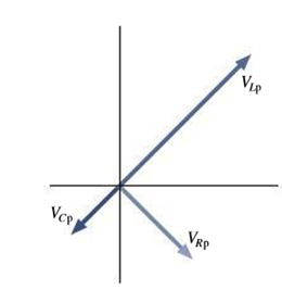
FIGURE 28.26 Problem 53
Expert Solution & Answer
Want to see the full answer?
Check out a sample textbook solution
Chapter 28 Solutions
Essential University Physics
Ch. 28.1 - What are the peak voltage and angular frequency of...Ch. 28.2 - Prob. 28.2GICh. 28.3 - You have an LC circuit that oscillates at a...Ch. 28.4 - You measure the capacitor and inductor voltages in...Ch. 28.5 - A resistor and capacitor are connected in series...Ch. 28.6 - A distribution line in a city supplies AC power at...Ch. 28 - Whats meant by the statement, A capacitor acts...Ch. 28 - Why does it make sense that inductive reactance...Ch. 28 - The same AC voltage appears across a capacitor and...Ch. 28 - When a particular inductor and capacitor are...
Ch. 28 - An inductor and capacitor are connected in series...Ch. 28 - Why is Equation 28.5 not a full description of the...Ch. 28 - The applied voltage in a series RLC circuit lags...Ch. 28 - The voltage across two components in series is...Ch. 28 - If you measure the rms voltages across the...Ch. 28 - A step-up transformer increases voltage, or energy...Ch. 28 - Much of Europe uses AC power at 230 V rms and 50...Ch. 28 - An AC current is given by I = 495 sin(9.43t), with...Ch. 28 - Prob. 13ECh. 28 - Find the rms current in a 1.0-F capacitor...Ch. 28 - A 470- resistor, 10-F capacitor, and 750-mH...Ch. 28 - Find the reactance of a 3.3-F capacitor at (a) 60...Ch. 28 - A 15-F capacitor carries 1.4 A rms. Whats its...Ch. 28 - A capacitor and a 1.8-k resistor pass the same...Ch. 28 - A 50-mH inductor is connected across a 10-V rms AC...Ch. 28 - Find the resonant frequency of an LC circuit...Ch. 28 - Prob. 21ECh. 28 - Your sister whos building the radio (Chapter 27...Ch. 28 - An LC circuit with a 20-F capacitor oscillates...Ch. 28 - A series RLC circuit has R = 75 k, L = 20 mH, and...Ch. 28 - Find the impedance at 10 kHz of a circuit...Ch. 28 - A series RLC circuit has R = 18 k, C = 14 F, and L...Ch. 28 - If the peak voltage applied to produce the curves...Ch. 28 - An electric drill draws 4.6 A rms at 120 V rms. If...Ch. 28 - A 40-W fluorescent lamp has power factor 0.85 and...Ch. 28 - An electric water heater draws 20 A rms at 240 V...Ch. 28 - For safety, medical equipment connected to...Ch. 28 - Youre planning a semester in China, so you want to...Ch. 28 - Example 28.2: In a European application, a...Ch. 28 - Example 28.2: A 0.470-μF capacitor and a 144-μH...Ch. 28 - Example 28.2: A radio transmitter applies 480 V...Ch. 28 - Example 28.2: You’re building a radio transmitter...Ch. 28 - Example 28.4: A crossover network in a loudspeaker...Ch. 28 - Example 28.4: The midrange speaker in a...Ch. 28 - Example 28.4: In Fig. 28.25, take and . A...Ch. 28 - For the circuit of Fig. 28.25. use a phasor...Ch. 28 - (a) A 2.2-H inductor is connected across 120-V...Ch. 28 - A 2.0-F capacitor has 1.0-k reactance. (a) Whats...Ch. 28 - Show that the unit of both capacitive and...Ch. 28 - Electroencephalography (EEG) elucidates brain...Ch. 28 - A 2.2-nF capacitor and one of unknown capacitance...Ch. 28 - Connections to the body for electrocardiography...Ch. 28 - The FM radio band covers the frequency range 88108...Ch. 28 - An LC circuit includes a 0.025-F capacitor and a...Ch. 28 - Prob. 49PCh. 28 - The 2420-F capacitor in Fig. 28.25 is initially...Ch. 28 - A damped LC circuit consists of a 0.15-F capacitor...Ch. 28 - A damped RLC circuit includes a 5.0- resistor and...Ch. 28 - An RLC circuit includes a 1.5-H inductor and a...Ch. 28 - The table below shows the ratio of peak voltage to...Ch. 28 - Figure 28.26 shows the phasor diagram for an RLC...Ch. 28 - An AC voltage of fixed amplitude is applied across...Ch. 28 - A series RLC circuit has resistance 127 and...Ch. 28 - A series RLC circuit has power factor 0.764 and...Ch. 28 - Youre Chief Financial Officer for a power company,...Ch. 28 - Prob. 60PCh. 28 - A power supply like that of Fig. 28.23 is supposed...Ch. 28 - An RLC circuit includes a 3.3-F capacitor and a...Ch. 28 - A series RLC circuit with R = 1.3 , L = 27 mH, and...Ch. 28 - Differentiate Equation 28.9 to find the current in...Ch. 28 - Find a second frequency where the current in the...Ch. 28 - Two capacitors are connected in parallel across a...Ch. 28 - A sine-wave generator with 15.0-V peak output is...Ch. 28 - For RLC circuits in which the resistance isnt too...Ch. 28 - A triangle wave swings linearly between voltages...Ch. 28 - Substitute the expression for q(t) in Equation...Ch. 28 - Although the maximum current flows in the speaker...Ch. 28 - A filter is a circuit designed to pass AC signals...Ch. 28 - A filter is a circuit designed to pass AC signals...Ch. 28 - A filter is a circuit designed to pass AC signals...Ch. 28 - A filter is a circuit designed to pass AC signals...
Additional Science Textbook Solutions
Find more solutions based on key concepts
The setup depicted in Figure 4.6 is used in a diffraction experiment using X-rays of 0.26 nm wavelength. Constr...
Modern Physics
3. * Consider again the turntable described in the last problem. Determine the magnitudes of the rotational acc...
College Physics
Give an example of a process in which no heat is added to a system, but its temperature increases. Then give an...
An Introduction to Thermal Physics
31. On an air track, a 400.0 g glider moving to the right at 2.00 m/s collides elastically with a 500.0 g glide...
College Physics (10th Edition)
The force, when you push against a wall with your fingers, they bend.
Conceptual Physics (12th Edition)
17. (I) How much work is required to stop an electron (m = 9.11 x 10⁻³¹ kg) which is moving with a speed of 1.1...
Physics: Principles with Applications
Knowledge Booster


Learn more about
Need a deep-dive on the concept behind this application? Look no further. Learn more about this topic, physics and related others by exploring similar questions and additional content below.Similar questions
- A series RLC circuit has resistance R = 50.0 and inductance L. = 0.500 H. (a) Find the circuits capacitance C if the voltage source operates at a frequency of f = 60.0 Hz and the impedance is Z = R = 50.0 . (b) What is the phase angle between the current and the voltage?arrow_forwardConsider the Filter circuit shown in Figure P33.56. (a) Show that the ratio of the amplitude of the output voltage to that of the input voltage is to that of input voltage is VoutVin=1/CR2+(1C)2 (b) What value does this ratio approach as the frequency decreases toward zero? (c) What value does this ratio approach as the frequency increases without limit? (d) At what frequency is the ratio equal to one-half?arrow_forwardProblems 71 and 72 paired. Figure P33.71 shows a series RLC circuit with a 25.0- resistor, a 430.0-mH inductor, and a 24.0-F capacitor connected to an AC source with Vmax = 60.0 V operating at 60.0 Hz. What is the maximum voltage across the a. resistor, b. inductor, and c. capacitor in the circuit? FIGURE P33.71 Problems 71 and 72.arrow_forward
- A 1.5k resistor and 30-mH inductor are connected in series, as below, across a120-V(rms)ac power source oscillating at 60-Hz frequency. (a) Find the current in the circuit. (b) Find the voltage drops across the resistor and inductor. (C) Find the impedance of the circuit. (d) Find the power dissipated in the resistor. (e) Find the power dissipated in the inductor. (1) Find the power produced by the source.arrow_forwardIn a series RLC circuit with a maximum current of 0.250 A, an AC source with Vmax= 115 V operating at 60.0 Hz is connected to a 325-mH inductor, a 7.50-F capacitor, and a resistor with unknown resistance R. Draw a phasor diagram for this circuit, including the current, the potential difference across each of the circuit elements, and the source emf. Draw your diagram with the current phasor pointing upward along the vertical axis.arrow_forwardReview. The voltage phasor diagram for a certain series RLC circuit is shown in Figure P33.59. The resistance of the circuit is 75.0 , and the frequency is 60.0 Hz. Find (a) the maximum voltage Vmax, (b) the phase angle , (c) the maximum current, (d) the impedance, (e) the capacitance and (f) the inductance of the circuit, and (g) the average power delivered to the circuit.arrow_forward
- In a purely inductive AC circuit as shown in Figure P21.15, Vmax = 100. V. (a) The maximum current is 7.50 A at 50.0 Hz. Calculate the inductance L. (b) At what angular frequency is the maximum current 2.50A? Figure p21.15arrow_forwardAn ac source of voltage amplitude 10 V delivers electric energy at a rate of 0.80 W when its current output is 2.5 A. What is the phase angle between the emf and the current?arrow_forwardCalculate the reactance of a 5.0F capacitor at (a) 60 Hz, (b) 600 Hz, and (c) 6000 Hz.arrow_forward
- A 40-mH inductor is connected to a 60-Hz AC source whose voltage amplitude is 50 V. If an AC voltmeter is placed across the inductor, what does it read?arrow_forwardAn RLC series circuit has a 2.50 (resistor, a 100 (H inductor, and an 80.0 (F capacitor. (a) Find the circuit's impedance at 120 Hz. (b) Find the circuit’s impedance at 5.00 kHz. (c) If the voltage source has Vrms = 5.60 V, what is Irms at each frequency? (d) What is the resonant frequency of the circuit? (e) What is Irms at resonance?arrow_forwardP33.80a shows a parallel RLC circuit. The instantaneous voltages (and rms voltages) across each of the three circuit elements are the same, and each is in phase with the current in the resistor. The currents in C and L lead or lag the current in the resistor as shown in the current phasor diagram, Figure P33.80b. (a) Show that the rms current delivered by the source is Irms=Vrms[1R2+(C1L)2]12 (b) Show that the phase angle between Vrms and Irms is given by tan=R(1Xc1XL)arrow_forward
arrow_back_ios
SEE MORE QUESTIONS
arrow_forward_ios
Recommended textbooks for you
 Physics for Scientists and Engineers with Modern ...PhysicsISBN:9781337553292Author:Raymond A. Serway, John W. JewettPublisher:Cengage Learning
 Physics for Scientists and EngineersPhysicsISBN:9781337553278Author:Raymond A. Serway, John W. JewettPublisher:Cengage Learning
 Physics for Scientists and Engineers, Technology ...PhysicsISBN:9781305116399Author:Raymond A. Serway, John W. JewettPublisher:Cengage Learning
 Physics for Scientists and Engineers: Foundations...PhysicsISBN:9781133939146Author:Katz, Debora M.Publisher:Cengage Learning
 College PhysicsPhysicsISBN:9781305952300Author:Raymond A. Serway, Chris VuillePublisher:Cengage Learning
 College PhysicsPhysicsISBN:9781285737027Author:Raymond A. Serway, Chris VuillePublisher:Cengage Learning
Physics for Scientists and Engineers with Modern ...
Physics
ISBN:9781337553292
Author:Raymond A. Serway, John W. Jewett
Publisher:Cengage Learning
Physics for Scientists and Engineers
Physics
ISBN:9781337553278
Author:Raymond A. Serway, John W. Jewett
Publisher:Cengage Learning
Physics for Scientists and Engineers, Technology ...
Physics
ISBN:9781305116399
Author:Raymond A. Serway, John W. Jewett
Publisher:Cengage Learning
Physics for Scientists and Engineers: Foundations...
Physics
ISBN:9781133939146
Author:Katz, Debora M.
Publisher:Cengage Learning
College Physics
Physics
ISBN:9781305952300
Author:Raymond A. Serway, Chris Vuille
Publisher:Cengage Learning
College Physics
Physics
ISBN:9781285737027
Author:Raymond A. Serway, Chris Vuille
Publisher:Cengage Learning
Introduction To Alternating Current; Author: Tutorials Point (India) Ltd;https://www.youtube.com/watch?v=0m142qAZZpE;License: Standard YouTube License, CC-BY