
Loose Leaf for Engineering Circuit Analysis Format: Loose-leaf
9th Edition
ISBN: 9781259989452
Author: Hayt
Publisher: Mcgraw Hill Publishers
expand_more
expand_more
format_list_bulleted
Concept explainers
Videos
Textbook Question
Chapter 2, Problem 36E
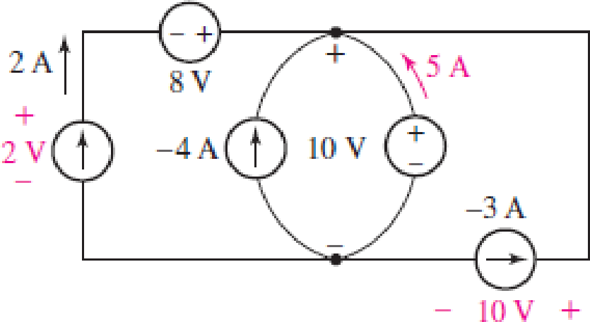
Some of the ideal sources in the circuit of Fig. 2.33 are supplying positive power, and others are absorbing positive power. Determine which are which, and show that the algebraic sum of the power absorbed by each element (taking care to preserve signs) is equal to zero.
FIGURE 2.33
Expert Solution & Answer
Want to see the full answer?
Check out a sample textbook solution
Students have asked these similar questions
Please let me give solution
Find the Vpeak of the Vout Value of the circuit below during the positive half cycle.
V2
Silicon
()
8
R1
V1
AC
24
V3
6
Vout
Determine V, in the circuit
652
9 V
V.
3 V
Give your answer in V [Volts], write the answer without the unit.
292
www
Chapter 2 Solutions
Loose Leaf for Engineering Circuit Analysis Format: Loose-leaf
Ch. 2.1 - A krypton fluoride laser emits light at a...Ch. 2.1 - A typical incandescent reading lamp runs at 60 W....Ch. 2.2 - In the wire of Fig. 2.7, electrons are moving left...Ch. 2.2 - For the element in Fig. 2.11, v1 = 17 V. Determine...Ch. 2.2 - Prob. 6PCh. 2.2 - Determine the power being generated by the circuit...Ch. 2.2 - Determine the power being delivered to the circuit...Ch. 2.2 - Your rechargeable smartphone battery has a voltage...Ch. 2.3 - Find the power absorbed by each element in the...Ch. 2.4 - Prob. 11P
Ch. 2.4 - Prob. 12PCh. 2.4 - The power absorbed by the resistor if i = 3 nA and...Ch. 2 - Convert the following to engineering notation: (a)...Ch. 2 - Convert the following to engineering notation:...Ch. 2 - Prob. 3ECh. 2 - Prob. 4ECh. 2 - Convert the following to SI units, taking care to...Ch. 2 - Prob. 6ECh. 2 - It takes you approximately 2 hours to finish your...Ch. 2 - A certain krypton fluoride laser generates 15 ns...Ch. 2 - Your recommended daily food intake is 2500 food...Ch. 2 - An electric vehicle is driven by a single motor...Ch. 2 - Under insolation conditions of 500 W/m2 (direct...Ch. 2 - A certain metal oxide nanowire piezoelectricity...Ch. 2 - Assuming a global population of 9 billion people,...Ch. 2 - The total charge flowing out of one end of a small...Ch. 2 - Prob. 15ECh. 2 - The total charge stored on a 1 cm diameter...Ch. 2 - A mysterious device found in a forgotten...Ch. 2 - A new type of device appears to accumulate charge...Ch. 2 - The current flowing through a tungsten-filament...Ch. 2 - The current waveform depicted in Fig. 2.28 is...Ch. 2 - The current waveform depicted in Fig. 2.29 is...Ch. 2 - A wind power system with increasing windspeed has...Ch. 2 - Two metallic terminals protrude from a device. The...Ch. 2 - The convention for voltmeters is to use a black...Ch. 2 - Determine the power absorbed by each of the...Ch. 2 - Determine the power absorbed by each of the...Ch. 2 - Determine the unknown current for the circuit in...Ch. 2 - A constant current of 1 ampere is measured flowing...Ch. 2 - Determine the power supplied by the leftmost...Ch. 2 - The currentvoltage characteristic of a silicon...Ch. 2 - A particular electric utility charges customers...Ch. 2 - The Tilting Windmill Electrical Cooperative LLC...Ch. 2 - A laptop computer consumes an average power of 20...Ch. 2 - You have just installed a rooftop solar...Ch. 2 - Prob. 35ECh. 2 - Some of the ideal sources in the circuit of Fig....Ch. 2 - Prob. 37ECh. 2 - Refer to the circuit represented in Fig. 2.35,...Ch. 2 - Prob. 39ECh. 2 - Prob. 40ECh. 2 - Prob. 41ECh. 2 - Determine the magnitude of the current flowing...Ch. 2 - Real resistors can only be manufactured to a...Ch. 2 - (a) Sketch the current-voltage relationship...Ch. 2 - Prob. 45ECh. 2 - Figure 2.38 depicts the currentvoltage...Ch. 2 - Examine the I-V characteristics in Fig. 2.38....Ch. 2 - Determine the conductance (in siemens) of the...Ch. 2 - Determine the magnitude of the current flowing...Ch. 2 - A 1% tolerance 1 k resistor may in reality have a...Ch. 2 - Utilize the fact that in the circuit of Fig. 2.39,...Ch. 2 - For the circuit in Fig. 2.39, suppose that the...Ch. 2 - For each of the circuits in Fig. 2.40, find the...Ch. 2 - Sketch the power absorbed by a 100 resistor as a...Ch. 2 - You built an android that has a subcircuit...Ch. 2 - Using the data in Table 2.4, calculate the...Ch. 2 - Prob. 58ECh. 2 - Prob. 59ECh. 2 - Prob. 60ECh. 2 - The resistance values in Table 2.4 are calibrated...Ch. 2 - Prob. 62ECh. 2 - Prob. 63ECh. 2 - The network shown in Fig. 2.42 can be used to...Ch. 2 - Prob. 65ECh. 2 - An LED operates at a current of 40 mA, with a...Ch. 2 - You have found a way to directly power your wall...
Knowledge Booster


Learn more about
Need a deep-dive on the concept behind this application? Look no further. Learn more about this topic, electrical-engineering and related others by exploring similar questions and additional content below.Similar questions
- Ohm's law describes the relation of voltage difference and current passing across an element. Select one: True Falsearrow_forwardOhm's law describes the relation of energy and power dissipated by an element. Select one: True Falsearrow_forwardHW1.1 - Calculate the equivalent resistance Rab at terminals a-b for each of the circuits Figure.1(a) and Figure. 1(b). 30 2 402 82 92 a o ww ww 20 2 60 2 52 150 102 11 2 202 42 bo w 102 50 2 (a) bo W- Figure.1 70 2 80 2 (b) HW1.2 – Find the values in the Figure.1 if the current through the 35 Q resistor is 5 A. 162 ww (a) the voltage VA, |SA : 30Ω (b) the voltage Vs , 15Ω (e) the power Ps. 10Ω 35Ω Ps 60 Ω (c) the current IB, 30Ω (e) the power Pg. Figure.2 HW1.3 – Calculate the voltages Vo and Vab , the currents io and ix, the power of Psı in the Figure.3 via Ohm's Law, KVL, and KCL. The voltage sources of the circuit are Vs1 = 250 Volt, Vs2= 50 Volt. 252 170 int 5.ix 480 Vab Figure.3 ww ww ww wwarrow_forward
- This is a three-part problem. The current i0 in the figure attached is 2 A. a) Find i1. b) Find the power dissipated in each resistor c) Verify that the total power dissipated in the circuit equals the power developed by the 80 V source.arrow_forwardFind the R₁ for maximum power transfer. Find the max power transferred to R₁. Is (1) Given Variables: Is: 3 A R1: 46 ohm R2: 23 ohm Determine the following: RL (ohm): R₁ Pmax (W) : ww R₂ ww R₁arrow_forwardA pure resistor in an AC circuit behaves in exactly the same way as in the equivalent of DC circuit. Select one: O True O False Three light bulbs L1 = 20 W, L 2= 7 W, L 3= 23 W, are connected to a 11 V battery as shown in Figure below. The current flowing through L 3 bulb is L2 W P) Li W L3 W 4.55 A 2.45 mA 2.73 A O 1.82 mAarrow_forward
- Find the Vpeak of the Vout Value of the circuit below during the negative half cycle. V2 Silicon 8 R1 v1 AC 24 V3 6 Voutarrow_forwardGiven the circuit of Figure Q2, if the frequency of the supply is 50 Hz, determine the current, 1, I1 and I2. 63.66 mH 202 I I2 I 100VZ0°( 26.53 µF Figure Q2arrow_forward1) A battery of emf V and internal resistance r is connected in series with an ammeter with resistance TA and a resistor R. The current measured by the ammeter is I. a) Find the current through the circuit if the resister R is doubled to 2R. Express your answer in terms of ra, A. r, and R. (b) What is the maximum value of the ammeter resistance ra so that 90% of the power will be dissipated at the resister R in the circuit for R-5.5 2 and V=7.5V, r-0.2 2?arrow_forward
- From the following circuit, calculate the equivalent resistor that the source would observe, E. Also calculate the voltage and current in the 2-ohm resistor. Indicate what is the power dissipated in that resistor. Consider that you can redraw the circuit or make reductions where appropriate. E 7 ohm w 24 v 2 ohm 4 ohm 24 ohm 12 ohm 12 ohm. 6 ohmarrow_forwardQ1 Answer by True or False the following statement 4- The algebraic sum of voltages around any elosed path in a network is equal to one 5- The basic laws for analyzing an electric circuit are Newtons laws 6- Relation between currents according to KCL for a node with two input current (I & I:)and two outputs (ls & la) is I1-1+Is+le=0 7- A 3-ohm and 6-ohm resistor are connected in parallel, and a 10-ohm resistor is in series with the combination. When 36 volts is applied to the three resistors, the total current in the circuit is 2 amps. 8- KCL and KVL is limited to write two equations for a particular circuit. 9- When assigning branch currents, you need not be concerned with the direction you choose. 10- For the circuit shown below (Fig.1) the value of resistance is 17.5 ohms 5 ohm 2 A 70 v 7 ohm R? Fig.1arrow_forwardQ1: By using any method for simplifying electric network , Find the current of 1Q -: resistor V2 3 V T V3arrow_forward
arrow_back_ios
SEE MORE QUESTIONS
arrow_forward_ios
Recommended textbooks for you
 Introductory Circuit Analysis (13th Edition)Electrical EngineeringISBN:9780133923605Author:Robert L. BoylestadPublisher:PEARSON
 Delmar's Standard Textbook Of ElectricityElectrical EngineeringISBN:9781337900348Author:Stephen L. HermanPublisher:Cengage Learning
 Programmable Logic ControllersElectrical EngineeringISBN:9780073373843Author:Frank D. PetruzellaPublisher:McGraw-Hill Education
 Fundamentals of Electric CircuitsElectrical EngineeringISBN:9780078028229Author:Charles K Alexander, Matthew SadikuPublisher:McGraw-Hill Education
 Electric Circuits. (11th Edition)Electrical EngineeringISBN:9780134746968Author:James W. Nilsson, Susan RiedelPublisher:PEARSON
 Engineering ElectromagneticsElectrical EngineeringISBN:9780078028151Author:Hayt, William H. (william Hart), Jr, BUCK, John A.Publisher:Mcgraw-hill Education,
Introductory Circuit Analysis (13th Edition)
Electrical Engineering
ISBN:9780133923605
Author:Robert L. Boylestad
Publisher:PEARSON
Delmar's Standard Textbook Of Electricity
Electrical Engineering
ISBN:9781337900348
Author:Stephen L. Herman
Publisher:Cengage Learning
Programmable Logic Controllers
Electrical Engineering
ISBN:9780073373843
Author:Frank D. Petruzella
Publisher:McGraw-Hill Education
Fundamentals of Electric Circuits
Electrical Engineering
ISBN:9780078028229
Author:Charles K Alexander, Matthew Sadiku
Publisher:McGraw-Hill Education
Electric Circuits. (11th Edition)
Electrical Engineering
ISBN:9780134746968
Author:James W. Nilsson, Susan Riedel
Publisher:PEARSON
Engineering Electromagnetics
Electrical Engineering
ISBN:9780078028151
Author:Hayt, William H. (william Hart), Jr, BUCK, John A.
Publisher:Mcgraw-hill Education,
How do Electric Transmission Lines Work?; Author: Practical Engineering;https://www.youtube.com/watch?v=qjY31x0m3d8;License: Standard Youtube License