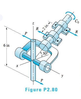
The figure shows one-half of a universal coupling known as the Hooke's joint. The coupling is acted on by the three couples shown: (a) the input couple consisting of forces of magnitude P , (b) the output couple C 0 , and (c) the couple formed by bearing reactions of magnitude R . If the resultant of these couples is zero, compute R and C 0 for P = 750 lb .
The figure shows one-half of a universal coupling known as the Hooke's joint. The coupling is acted on by the three couples shown: (a) the input couple consisting of forces of magnitude P , (b) the output couple C 0 , and (c) the couple formed by bearing reactions of magnitude R . If the resultant of these couples is zero, compute R and C 0 for P = 750 lb .
The figure shows one-half of a universal coupling known as the Hooke's joint. The coupling is acted on by the three couples shown: (a) the input couple consisting of forces of magnitude P, (b) the output couple
C
0
,
and (c) the couple formed by bearing reactions of magnitude R. If the resultant of these couples is zero, compute R and
C
0
for
P
=
750
lb
.
Expert Solution
To determine
(i)
The input couple consisting of forces of magnitude P.
Difficult Problem:
If magnitude of MA is 1200 kN – m and the distance between A and B is 3 m, what is the
force FB and distance d so that the system shown at the right is equivalent to a force-couple
system acting at point D, where the horizontal component of this force is R = 112 kN to the
right and the corresponding couple is 635 counterclockwise.
60 kN
30
50 kN
2 m
MA
60°
15°
200 kN
m
100 kN
4 m
Fs
2 m
200 kN
30
60 kN
-3 m
Example 1: Determine the resultant moment of the three couples acting on the
Plate shown.
F= 200 N
F= 300 N
A
0.5 m
F = 450 N
0.4 m
0.3 m
F= 450 N
F= 300 N
F= 200 N
As shown, the perpendicular distances between
each pair of couple forces 0.5 m, 0.4 m, and 0.3
m. Assuming the CCW couple as positive, we
have:
MR =EM; MR =-(200 N)(0.4 m)+(450 N)(0.3 m)- (300 N)(0.5 m)
=-95 N.m
or = 95 N.m CW
A solid cylindrical shaft anchored to the wall at point O is subjected to 70 N and 85 N couples and a
concentrated moment at point E. Determine the resultant couple moment. Hint: You can do this in
either of two ways by applying (1) a "scalar" approach by evaluating the individual moments of the x, y,
and z components of the 70N and 85N forces, taking positive moments to be in the positive coordinate
directions according to the right-hand rule., or (2) the "vector approach" utilizing 3D position vectors
using the general cross product definition for the force moment.
70 N
0.8 m
1.2 m
2
6
70 N
1.2 m
0.8 m
9
85 N 12
9
12
-1.2m 1.5m
8
D
85 N
C
8
E
200 N·m
X
Chapter 2 Solutions
International Edition---engineering Mechanics: Statics, 4th Edition
Need a deep-dive on the concept behind this application? Look no further. Learn more about this topic, mechanical-engineering and related others by exploring similar questions and additional content below.
Mechanical Design (Machine Design) Clutches, Brakes and Flywheels Intro (S20 ME470 Class 15); Author: Professor Ted Diehl;https://www.youtube.com/watch?v=eMvbePrsT34;License: Standard Youtube License


 International Edition---engineering Mechanics: St...Mechanical EngineeringISBN:9781305501607Author:Andrew Pytel And Jaan KiusalaasPublisher:CENGAGE L