
ANALYSIS+DESIGN OF LINEAR CIRCUITS(LL)
8th Edition
ISBN: 9781119235385
Author: Thomas
Publisher: WILEY
expand_more
expand_more
format_list_bulleted
Concept explainers
Videos
Textbook Question
Chapter 1, Problem 1.9P
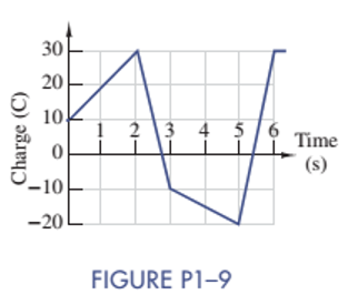
Figure P1-9 shows a plot of the net positive charge flowing in a wire versus time. Sketch the corresponding current during the same period of time.
Expert Solution & Answer
Want to see the full answer?
Check out a sample textbook solution
Students have asked these similar questions
Steady current circulation is desired for a lamp connected in a circuit to light. For this, explain how a stable current will occur from any part of the circuit with the conservation law of the charge.
Give me detail pls.
The charge entering a certain element is shown in the given figure, where A = 70. Find the current at 1 ms, 6 ms, and 10 ms.
The current at 1 ms is _____ A.
The current at 6 ms is _____ A.
The current at 10 ms is ______ A.
P1.15. A copper wire has a diameter of 2.05 mm
and carries a current of 15 A due solely to
clectrons. (These values are common in
residential wiring.) Each electron has a
charge of -1.60 × 10⁻¹⁹ C. Assume that the
free-electron (these are the electrons capable
of moving through the copper) concentration
in copper is 1029 electrons/m'. Find the
average velocity of the electrons in the wire.
Chapter 1 Solutions
ANALYSIS+DESIGN OF LINEAR CIRCUITS(LL)
Ch. 1 - Given an electrical quantity described in terms of...Ch. 1 - Express the following quantities to the nearest...Ch. 1 - An ampere-hour (Ah) meter measures the time...Ch. 1 - Electric power companies measure energy...Ch. 1 - Fill in the blanks in the following statements. To...Ch. 1 - Which of the two entries is larger? 1000...Ch. 1 - A wire carries a constant current of 30A. How many...Ch. 1 - The net positive charge flowing through a device...Ch. 1 - Figure P1-9 shows a plot of the net positive...Ch. 1 - The net negative charge flowing through a device...
Ch. 1 - A cell phone charger outputs 9.6 V and is...Ch. 1 - For 0t5s, the current through a device is...Ch. 1 - The charge flowing through a device is...Ch. 1 - The 12-V automobile battery in Figure P1-14 has an...Ch. 1 - The current through a device is zero for t0 and is...Ch. 1 - A string of holiday lights is protected by a 12A...Ch. 1 - When illuminated the relationship for a photocell...Ch. 1 - A new 6-V alkaline lantern battery delivers...Ch. 1 - The maximum current allowed by a device's power...Ch. 1 - Traffic lights are being converted from...Ch. 1 - Two electrical devices are connected as shown in...Ch. 1 - Figure P1-22 shows an electric circuit with a...Ch. 1 - Figure P1-22 shows an electric circuit with a...Ch. 1 - In Figure P1-24 the voltage v2 is 10 V and v4 is 5...Ch. 1 - For t0, the voltage across and power absorbed by a...Ch. 1 - Repeat Problem 1-22 using MATLAB to perform the...Ch. 1 - Using the passive sign convention, the voltage...Ch. 1 - Power Ratio (PR) in dB A stereo amplifier takes...Ch. 1 - AC to DC Converter A manufacturer's data sheet for...Ch. 1 - Charge-Storage Device A capacitor is a...Ch. 1 - Compute Data Sheet A manufacturer's data sheet for...Ch. 1 - Light Source Comparison A Today people have three...
Additional Engineering Textbook Solutions
Find more solutions based on key concepts
For the circuit shown, use the node-voltage method to find v1, v2, and i1.
How much power is delivered to the c...
Electric Circuits (10th Edition)
For the circuit shown, use the node-voltage method to find v1, v2, and i1.
How much power is delivered to the c...
Electric Circuits. (11th Edition)
The switch in the bottom loop of Fig. P6.1 is closed at t = 0 and then opened at a later time t1. What is the d...
Fundamentals of Applied Electromagnetics (7th Edition)
Find Vab in the network in Fig. P2.80.
Basic Engineering Circuit Analysis
Determine one of the unknown currents of Fig. 6.96, using the current divider rule. Determine the other current...
Introductory Circuit Analysis (13th Edition)
Consider the circuit shown in Figure P1.63. Find the current iR flowing through the resistor. Find the power fo...
Electrical Engineering: Principles & Applications (7th Edition)
Knowledge Booster


Learn more about
Need a deep-dive on the concept behind this application? Look no further. Learn more about this topic, electrical-engineering and related others by exploring similar questions and additional content below.Similar questions
- Question 3 a. Some materials exhibit the property of superconductivity under certain conditions. State what is meant by superconductivity and explain the required conditions for the material to become superconducting. b. The diagram below shows the cross-section of a cable consisting of parallel filaments that can be made superconducting, embedded in a cylinder of copper. copper cylinder filament The cross-sectional area of the copper in the cable is 2.28 x 10⁻⁷ m². The resistance of the copper in a 1.0 m length of the cable is 0.075 N. Calculate the resistivity of the copper, stating an appropriate unit. State and explain the what happen to the resistance of the cable when the embedded filaments of wire are made superconductive? i.arrow_forwardQuestion 5 a) i. A piece of pencil lead is connected in series with an ammeter and a power supply. The power supply is turned on. After a few minutes, although the potential difference across the pencil lead does not change, the current in the circuit increases significantly. Explain why the current increases. The current /in a length of aluminum of cross-sectional area A is given by the formula I= nevA ii. e is the charge on an electron. Show that the units on the left-hand side of the equation are consistent with those on the right-hand side.arrow_forwardA negative charge of -0.0005 C exerts an attractive force of 9.0 N on a second charge that is 10 m. away. What is the magnitude of the second charge?arrow_forward
- Discuss the relationship between voltage break down and humidity, temperature and distance explain with curvearrow_forwardDiagram of the problem, necessary formulas, clearance and numerical solution. A steady current of 0.5 A flows through a wire. How much charge passes through the wire in one minute?arrow_forwardthis is the ability of a material to conduct electricity a. impedane b. conductance c. reactance d. capacitancearrow_forward
- Sketch a graph of the voltage vs time for a 10V DC voltagearrow_forwardb. A piece of pencil lead is connected in series with an ammeter and a power supply. The power supply is turned on. After a few minutes, although the potential difference across the pencil lead does not change, the current in the circuit increases significantly. Explain why the current increases. c. Electric fields are caused by both point charges and by parallel plates with a potential difference across them. Describe the difference between the electric field caused by a point charge and the electric field between parallel plates. Your answer should include a diagram of each type of field and reference to electric field strength. Question 2arrow_forwardThe current in a circuit element is plotted in Figure P1.3-6. Determine the total charge that flows through the circuit element between 300 and 1200 μs.arrow_forward
- The potential at a point due to a charge of 100 micro coulomb at a distance of 9m will be?arrow_forwardProblem A potentiometer is an instrument for measuring an unknown voltage in comparison to a standard voltage. In the potentiometer shown in Figure 1.0 a 16.0-m stretch of wire AB is connected to a 9.00-V battery. The resistance per unit length of the wire is 16.0 0/mm. The movable contact P is at point B. An ammeter (circle with A inside) is connected to point A. 16.0 m A B www Figure: 1.0 A V = 9.00 Varrow_forward1.4 The charge cycle shown in Figure PL4 is an example of a three-rate charge. The current is held constant at 30 mA for 6 h. Then it is switched to 20 mA for the next 3 h. Find: a. The total charge transferred to the battery. b. The energy transferred to the battery.Page 58 Hint: Recall that energy w is the integral of power, or P = dw/dr. 1.7 V 1.2 V 9.6V 05 V 30 mA 20 mA Figure P14 3h 3h 6h 6h 9h 7arrow_forward
arrow_back_ios
SEE MORE QUESTIONS
arrow_forward_ios
Recommended textbooks for you
 Introductory Circuit Analysis (13th Edition)Electrical EngineeringISBN:9780133923605Author:Robert L. BoylestadPublisher:PEARSON
 Delmar's Standard Textbook Of ElectricityElectrical EngineeringISBN:9781337900348Author:Stephen L. HermanPublisher:Cengage Learning
 Programmable Logic ControllersElectrical EngineeringISBN:9780073373843Author:Frank D. PetruzellaPublisher:McGraw-Hill Education
 Fundamentals of Electric CircuitsElectrical EngineeringISBN:9780078028229Author:Charles K Alexander, Matthew SadikuPublisher:McGraw-Hill Education
 Electric Circuits. (11th Edition)Electrical EngineeringISBN:9780134746968Author:James W. Nilsson, Susan RiedelPublisher:PEARSON
 Engineering ElectromagneticsElectrical EngineeringISBN:9780078028151Author:Hayt, William H. (william Hart), Jr, BUCK, John A.Publisher:Mcgraw-hill Education,
Introductory Circuit Analysis (13th Edition)
Electrical Engineering
ISBN:9780133923605
Author:Robert L. Boylestad
Publisher:PEARSON
Delmar's Standard Textbook Of Electricity
Electrical Engineering
ISBN:9781337900348
Author:Stephen L. Herman
Publisher:Cengage Learning
Programmable Logic Controllers
Electrical Engineering
ISBN:9780073373843
Author:Frank D. Petruzella
Publisher:McGraw-Hill Education
Fundamentals of Electric Circuits
Electrical Engineering
ISBN:9780078028229
Author:Charles K Alexander, Matthew Sadiku
Publisher:McGraw-Hill Education
Electric Circuits. (11th Edition)
Electrical Engineering
ISBN:9780134746968
Author:James W. Nilsson, Susan Riedel
Publisher:PEARSON
Engineering Electromagnetics
Electrical Engineering
ISBN:9780078028151
Author:Hayt, William H. (william Hart), Jr, BUCK, John A.
Publisher:Mcgraw-hill Education,
Conductivity and Semiconductors; Author: Professor Dave Explains;https://www.youtube.com/watch?v=5zz6LlDVRl0;License: Standard Youtube License