
Videos
DATA You set up the circuit shown in Fig. 26.20. where C = 5.00 x 10⁻⁶F. At time t = 0. you close the switch and then measure the charge q on the capacitor as a function of the current i in the resistor. Your results are given in the table:
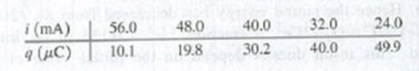
(a) Graph q as a function of i. Explain why the data points, when plotted this way, fall close to a straight line. Find the slope and y-intercept of the straight line that gives the best fit to the data.
(b) Use your results from part (a) to calculate the resistance R of the resistor and the emf ε of the battery, (c) At what time t after the switch is closed is the voltage across the capacitor equal to 10.0 V? (d) When the voltage across the capacitor is 4.00 V. what is the voltage across the resistor?

Trending nowThis is a popular solution!

Learn your wayIncludes step-by-step video

Chapter 26 Solutions
University Physics with Modern Physics (14th Edition)
Additional Science Textbook Solutions
Physics for Scientists and Engineers: A Strategic Approach, Vol. 1 (Chs 1-21) (4th Edition)
Conceptual Physical Science (6th Edition)
Conceptual Integrated Science
Physics: Principles with Applications
Tutorials in Introductory Physics
Cosmic Perspective Fundamentals


- An electrical circuit contains a capacitor of Z picofarads and a resistor of X ohms. If the capacitor is fully charged, and then the voltage is interrupted, in how much time will about 95% of its charge be transferred to the resistor? Show your calculations.arrow_forwardFour resistors (R1=A ohms, R2=B ohms, R3= C ohms, R4=D ohms) are connected in parallel. Find the current in R2 if the total voltage is 220 V. If the total voltage in the previous item is the potential difference between the two plates of a parallel plate capacitor, what is the capacitance if the amount of charge in one plate is A nanocoulombs?arrow_forwardConsider the circuit shown in the figure below. The four capacitors have capacitances C1=10μF, C2=13μF, C3=77μF, C4=19μF and are connected to a battery of voltage V=46Volts. When all capacitors are fully charged, determine the charge on C4. Express your answer in units of μF using zero decimal places.arrow_forward
- Consider the following. (a) A rectangular block has the dimensions ℓ ✕ w ✕ h. When a battery with a voltage V is connected across the end faces as shown in the left figure above, a current I1 flows through the circuit. If the same battery is connected across the top and bottom faces of the block as shown in the right figure, what is the current I2 that flows through the circuit? Give your answer in terms of I1. (Use the following as necessary: ℓ, w, h, I1) I2 = ? (b) Suppose ℓ = 4.20 cm, w = 2.2 cm, and h = 1.80 cm; the battery voltage is 1.5 V and I1 = 2.50 A, determine the value of I2. (A)arrow_forwardThe question is . A) What is the time constant for the circuit shown in the figure below if the value of of e=12.0 V, R=22.8ohm, and C= 88.1mF. B Suppose the switch is closed and the capacitor starts to charge. How much of the charge will be accumulated on each plate of the capacitor after 3 s of charging.. Submit answer the value of the charge (in mC, with two decimal places).arrow_forwardFind the current I through the circuit.I= (mA). Find the voltage across each resistor. Give your answer as a comma-separated list in unit of volt, as an absolute value. potential drops across R1, R2, R3, R4, and R5 (in volt, in order): What is the power supplied by the batteries—that is, the power dissipated or consumed by the circuit?P= (W).arrow_forward
- V + R w с The switch in the figure is thrown so that the battery is in series with the resistor and an uncharged capacitor. After 1.9 time constants, what is the charge on the capacitor in terms of the maximum charge, Qo? Supply the missing numerical factor below. Q(1.9T) = ( )Qoarrow_forwardUse the worked example above to help you solve this problem. An uncharged capacitor and a resistor are connected in series to a battery, as shown in the figure above. If E = 11.0 V, C = 5.50 μF, and R = 9.00 x 10⁵ , find the following. (a) the time constant of the circuit (b) the maximum charge on the capacitor μC (c) the charge on the capacitor after 6.10 s μC S (d) the potential difference across the resistor after 6.10 s (e) the current in the resistor at that time A EXERCISE Use the values from PRACTICE IT to help you work this exercise. (a) Find the charge on the capacitor after 2.20 s have elapsed. Q = C (b) Find the magnitude of the potential difference across the capacitor after 2.20 s. AVC V = R HINTS: GETTING STARTED 1 I'M STUCK! (c) Find the magnitude of the potential difference across the resistor at that same time. AV V =arrow_forwardConsider the circuit shown in the figure below. The four capacitors have capacitances C1=15μF, C2=16μF, C3=19μF, C4=13μF and are connected to a battery of voltage V=39Volts. When all capacitors are fully charged, determine the voltage across C4. Express your answer in units of Volts using one decimal place.arrow_forward
- Consider the circuit below. The switch is first closed and after a long time passes, the switch is reopened. Calculate the charge stored in the capacitor 7 x10s after the switch is reopened. Give your answer in x10 C to 3 sig figs. Switch R1 to 2 k2 20 V R, 3500 2 C: 100 µF R3 3 k2 GOarrow_forwardFour capacitors are connected as shown in Fig. 1. C1 = 4.50 μF, C2 = 7.50 μF, C3 = 2.50 μF and C4 = 4.50 μF. V = 20.0 V. (a) What is the equivalent capacitance for this circuit? Enter your answer in μF. (b) What is the voltage across capacitor 2? (c) What is the voltage across capacitor 3?arrow_forwardThe figure shows a circuit containing an electromotive force, a capacitor with a capacitance of C farads (F), and a resistor with a resistance of R ohms (2). The voltage drop across the capacitor is Q/C, where Q is the charge (in coulombs), so in this case we use the Kirchhoff's Law. + = E (t) But I = dQ/dt, so we have the formula below. dQ R- dt = E (t) Suppose the resistance is 20 n, the capacitance is 0.01 F, and a battery gives a constant voltage of 100 V. (a) Draw a direction field for this differential equation. (Do this on paper. Your instructor may ask you to turn in this sketch.) (b) What is the limiting value, Q of the charge? Q = (c) What is an equilibrium solution? Q = (d) If the initial charge is Q(0) = 0 C, use the direction field to sketch the solution curve. (Do this on paper. Your instructor may ask you to turn in this sketch.) (e) If the initial charge is Q(0) = 0 C, use Euler's method with step size 0.1 to estimate the charge, Q after half a second, Q(0.5). (Round…arrow_forward
 College PhysicsPhysicsISBN:9781305952300Author:Raymond A. Serway, Chris VuillePublisher:Cengage Learning
 University Physics (14th Edition)PhysicsISBN:9780133969290Author:Hugh D. Young, Roger A. FreedmanPublisher:PEARSON
 Introduction To Quantum MechanicsPhysicsISBN:9781107189638Author:Griffiths, David J., Schroeter, Darrell F.Publisher:Cambridge University Press
 Physics for Scientists and EngineersPhysicsISBN:9781337553278Author:Raymond A. Serway, John W. JewettPublisher:Cengage Learning
 Lecture- Tutorials for Introductory AstronomyPhysicsISBN:9780321820464Author:Edward E. Prather, Tim P. Slater, Jeff P. Adams, Gina BrissendenPublisher:Addison-Wesley
 College Physics: A Strategic Approach (4th Editio...PhysicsISBN:9780134609034Author:Randall D. Knight (Professor Emeritus), Brian Jones, Stuart FieldPublisher:PEARSON