
Videos
Using the circuit and transistor parameters of Example 13.11, and assuming threshold voltages of
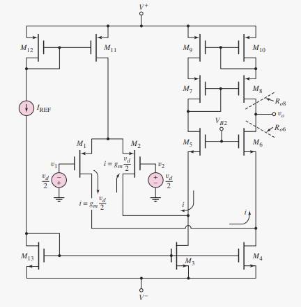
The maximum range of the common mode input voltage.
Answer to Problem 14.1TYU
Explanation of Solution
Given information:
Transistor parameters are:
Threshold voltage is
The given circuit is shown below.
Calculation:
The common mode input voltage range is given by
Let
For M1
Substituting the values,
Similarly for M4
Substituting the values,
Want to see more full solutions like this?
Chapter 14 Solutions
Microelectronics: Circuit Analysis and Design
Additional Engineering Textbook Solutions
Introductory Circuit Analysis (13th Edition)
Electric Circuits. (11th Edition)
Basic Engineering Circuit Analysis
ANALYSIS+DESIGN OF LINEAR CIRCUITS(LL)
Principles and Applications of Electrical Engineering
Engineering Electromagnetics


- Draw the circuit diagram of a resistance–capacitance coupled source followerarrow_forwardA Bipolar junction Transistor with curreat amplification factor being 100, Input Base current is 50μA. Collector voltage is 10 V and biasing voltage being +20 V. Find followings a. Collector current b. Resistance (R1) c. Collector voltage , Emitter voltage , Base Voltage & Collector-Emitter Voltage.arrow_forwardQ-3. Find the drain-source voltage, Vos, for the E- MOSFET circuit given below. The device parameters are: Ioss = 4 mA and Vm = 2 V. +15V Rp- 2k 4M R1 + Vps 2M R2arrow_forward
- A2 Briefly, but informatively, describe importance laser ablation in combination with ICP-MS in solid sample. Cite Reference/sarrow_forward4) Consider the clamping circuit below, assume Vref=3 V and Vin=5sin(wt) ..Draw the output voltage waveform. Clearly mark the max and min of the voltage.. Vrefarrow_forwardA certain npn silicon transistor has vBE=0.7 V for iB=0.1 mA at a temperature of 30°C. Sketch the input characteristic to scale at 30°C. What is the approximate value of vBE for iB = 0.1 mA at 180°C? (Use the rule of thumb that vBE is reduced in magnitude by 2 mV per degree increase in temperature.) Sketch the input characteristic to scale at 180°C.arrow_forward
- 14 - Which of the following is IC / IB (the ratio of collector current to base current) in a transistor?A) Dielectric coefficientB) Conversion rateC) Beta current gainD) Alpha current gainE) The conductivity coefficientarrow_forwardFind the performance parameters (FF, RF and n) for the Single phase bridge uncontrolled rectifier with RL load. If the phase voltage: Vph(t) = Vm sin(wt). Draw the circuit diagram and sketch the voltages and current waveforms.arrow_forwardIp B. Multiple choice questions 1. The characteristic of the voltage drop in on-state shown at right applies to: a) Thyristor (SCR) b) IGBT c) Diode d) MOSFET VDs= RDs.Ips 2. The structure shown at right is a structure of: DO N a) MOSFET b) Thyristor (SCR) c) BJT d) Diode VDS P-type substrate GO so Narrow_forward
- c. For the circuit shown in Figure, determine lc and VCB. Assume the transistor to be made of Silicon. Ic RE=1.6 kn Rc=1.1 kn EE=8 V Vcc= 20 varrow_forwardTransistors originally were made with germanium but modern transistors use silicon for its higher heat tolerance. Transistors amplify and switch signals. They can be analog or digital. Two prevalent transistors today are Metal-Oxide-Semiconductor Field Effect Transistors (MOSFET) and Bipolar Junction Transistors (BJT).In your own understanding in the field of electronics can you compare and contrast which one has merit over the other ?arrow_forwardDetermine VB, VE, VC, VCE, IB, IE, and IC in Figure. The 2N3904 is a general purpose transistor with a typical BDC 200 Vcc +30 V WWII VCE VB R₁ • 22 ΚΩ IC(mA) Chọn... * Chọn... * IB(UA) Chọn... * IE(MA) Chọn... ◆ Chọn... * Chọn... * Chọn... * VE VC R₂ ´ 10 ΚΩ www Rc 1.0 ΚΩ 2N3904 PDC=200 RE 1.0 ΚΩarrow_forward
 Introductory Circuit Analysis (13th Edition)Electrical EngineeringISBN:9780133923605Author:Robert L. BoylestadPublisher:PEARSON
 Delmar's Standard Textbook Of ElectricityElectrical EngineeringISBN:9781337900348Author:Stephen L. HermanPublisher:Cengage Learning
 Programmable Logic ControllersElectrical EngineeringISBN:9780073373843Author:Frank D. PetruzellaPublisher:McGraw-Hill Education
 Fundamentals of Electric CircuitsElectrical EngineeringISBN:9780078028229Author:Charles K Alexander, Matthew SadikuPublisher:McGraw-Hill Education
 Electric Circuits. (11th Edition)Electrical EngineeringISBN:9780134746968Author:James W. Nilsson, Susan RiedelPublisher:PEARSON
 Engineering ElectromagneticsElectrical EngineeringISBN:9780078028151Author:Hayt, William H. (william Hart), Jr, BUCK, John A.Publisher:Mcgraw-hill Education,