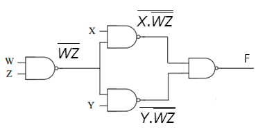
Write the output expression of the given logic diagram and show that the output expression is equal to (WZ)'(X+Y). X :D W Y


Q: a) Z = ABC + AB (A. C) b) Z=AC (ABD) + ABC.D+ABC
A:
Q: You want to design an arithmetic comparison unified logic circuit. (a) List the steps that you will…
A: 4 bit comparator
Q: 18. Derive the Boolean expression for the logic circuit below: a. CA + CB +CD A B b. C(A + B)D с.…
A:
Q: Design a logic circuit that satisfy the following Boolean relation. Sx + 2 when x 5 Where X is a…
A: Given equation for Y is Here, X is a 3-bit number, Let X =X2 X1 X0 The maximum value for X is 7,…
Q: Realize the Boolean expression X = AB + AB’C’ + BC’ and Y = BC + A’BC’ + ABC using Programmable…
A: Given: Brief description: In the above given question they have mentioned two Boolean expressions.…
Q: 3. a b m n C
A: Logic circuit
Q: Find the output Q of the logic circuit shown in below, for inputs shown below A= 110011 B-010101
A: A combinational circuit is one in which the various gates in the circuit, such as the encoder,…
Q: 1.2 For the given Boolean expression below, implement the logic circuit without simplifying it.…
A:
Q: a) Obtain the Truth table for the given Logic Expression with intermediate outputs. X=(AB +BC) + c…
A: Given expression is X=(AB+BC) +cbar
Q: 1.2 For the given Boolean expression below, implement the logic circuit without simplifying it.…
A:
Q: Home Work: Develop the truth table of the combinational logic circuit shown below. D Do D A В C
A:
Q: Multiplexer Mux: Realizing a Logic Function Given the Truth Table for a 3-input XOR: f 0 0 0 0 0 1 0…
A: We need to design the given circuit by using of 2 x 1 mux .
Q: Use De Morgan's Theorem for ((a' + bc)d' + e )' Create the logic diagram of the simplified function
A: In this question, we have to realize the function usingde morgans theoremThe function is given…
Q: The truth table of a combinational logic circuit with 3 inputs and 2 outputs is given in table B2.…
A:
Q: (1) Find out the logic expression of output Q for the circuit on the left. And prove this is…
A: Part 1: Consider the given circuit diagram,
Q: a) Design a circuit with 4 inputs A, B, C,D and a single output F. If A and B are equal, the output…
A:
Q: Make a logical circuit of the output equation F = A(B+C) and complete the following table based on…
A:
Q: For the logic circuit below complete the truth table. A D E 1 1 1 E B.
A:
Q: Question 2 (ii) Now sketch the same logic circuit as for (ii) above but only use NAND gates to…
A: First of all we must write the minterms from the given truth table. After writing the minterms we…
Q: A “vote taker” logic circuit forces its output toagree with a majority of its inputs. Such a circuit…
A: The “vote taker” logic circuit is drawn as below: P is AND combination of A and C. Thus P is…
Q: Q 5. Determine the expression of the given logic circuit and simplify it. (using De'Morgan's law /…
A: NOR Gate NOR gate is a type of universal gate in which when all the inputs are low then the output…
Q: Design a combinational circuit with three inputs x, y, and z and three outputs A, B, and C. When the…
A: The truth table for given combinational circuit is x y z A B C 0 0 0 0 1 0 0 0 1 0 1 1 0 1…
Q: Q2. Simplify the following Boolean expression to a minimum number of literals a nd draw the logic…
A: KARNOUGH-MAP- Minimization of logic expression using Boolean algebra becomes complex with an…
Q: Determine the outputs functions A and B as sums of product of the given Logic Circuit. You may use…
A: For upper 4:1 mux, A is an output, Inputs are, A0-zA1-zA2-zA3-z And selected lines are, So=y,S1=x…
Q: For the logic circuit shown below, the output (F) is 1 A B 2 6 F 8 1 10 11 D 12 13 14 15 F=AD+B'D'…
A: We need to find out simplified Boolean expression .
Q: Based on the given Boolean Expression below please simplify the expression and draw the logic…
A: The given expression is, Q=XYZ¯+XY¯Z+X¯YZ¯+XYZ¯ Boolean expression: This is logical…
Q: (a) Simplify the following Boolean expression 'A' and draw the logic diagram for the simplified…
A: In this answer we will try to simplify the given Boolean expression using different laws. We will…
Q: Write the output expression of the given logic diagram and show that the output expression is equal…
A: Fig: Give logic circuit A=XY
Q: Minimize the following Equation by using Karnaugh Map, then draw the final Logic Circuit of the…
A:
Q: Output expression of the logic diagram is, B O A + A'B' O A + A'B O A' + AB A + AB'
A: OR gate performs an Addition operation. AND gate performs Multiplication operation.
Q: 12.36 Determine the minimum expression for the following logic function, simplifying the expression:…
A: Given data, The value of function is given as, fA,B,C=(A+B)·A·B+A'·C+A·B'·C+B'.C'
Q: (a) Simplify the following Boolean expression 'A' and draw the logic diagram for the simplified…
A:
Q: 5. Obtain the simplest possible logic diagram for the circuit shown below: Output పుపుగు Dar lepo
A: The given circuit is:
Q: Show the Ladder logic program and the equivalent Function Block Diagram for the following Boolean…
A: Solution (1) Y=(A+B)·(C+D⊕A)·A The functional block diagram we will have for the given boolean…
Q: Write the Boolean expression of the output (X) for the below Logic Diagram. D. Answer:
A:
Q: Find the simplified sum-of-products representation of the function from the Karnaugh map shown in…
A:
Q: a Draw the Logic circuit of the following exPression ã o f=XYZ+XYZ t XX Then Simplify it
A: Simply the expression of function f= X'Y'Z+X'YZ+XY' Here using the Demorgon theorems A+BC= (A+B)…
Q: Design a logic circuit that count the number of occurs of the sequence 00 11 10 01 11
A:
Q: Express the output Y as a Boolean expression in inputs A and B for the logic circuit shown below: A…
A:
Q: 9. Determine the simplified output of the given logic diagram using appropriate laws and rules W. X.
A:
Q: Q2/ Realize the truth table and straight connection for the following statements NOTE: USE LOGISIM…
A: In a com-binational circuit the output only depends on the value of input regards of the previous…
Q: Using the simplified Boolean expression. The logic circuit is as shown in figure below AO- AB+ AB BO…
A: logic circuit is given
Q: Q2. Simplify the following Boolean expression to a minimum number of literals a nd draw the logic…
A: NOTE :- We’ll answer the first question since the exact one wasn’t specified. Please submit a new…
Q: For the given system: Draw the logic diagram (Do not use block design) Obtain the state table and…
A: Given: The input equation of the given system is: DA=QA'QB+QB'XDB=QAXZ=QAQBX To find: (a) Draw the…
Q: Find the output (F) of the logic circuit shown in figure below, for inputs A= 110011 B=010101…
A:
Q: 5. (a) Simplify the Boolean expression and draw the logic diagram that implements the simplified…
A: Explanation is given in the successive step
Q: Show the Ladder logic program and the equivalent Function Block Diagram for the following Boolean…
A:
Q: 1. Given the logic circuit diagram shown in Figure 1. Determine the Boolean expression for fhe…
A: Since you have asked multiple question, we will solve the first question for you. If you want any…
Q: Convert the given table into a logic diagram. Upload a photo of your output showing your solution.…
A: 2421 code is the Aiken code it is the complementary BCD code. In this Aiken code the four bits are…

The output expression is shown below,
The output expression is,

Step by step
Solved in 2 steps with 1 images


- Write a VHDL code for the following simple logic circuit. D- X1 X2 f X3Simplify the following Boolean expressions using Karnaugh Map and draw the logic circuits. f = wxyz + wxyz + wxyż + wxỹz + wxyz + wxyz + wxỹz + wãyzA three input logic functipn will provide a logic high output only when twp (and two only) of the inputs are logic highs. For all other input possibilities, a logic zero is provided on the output. What is the logic expression? A. Y=A'B'C+A'BC'+AB'C' B. Y=AB'C+A'BC+ABC' C. Y=AB'C+ABC+A'B'C' D. Y=ABC'+AB'C+A'B'C'
- Simplify the following expression using Karnaugh map and implement. Draw simplified logic diagram as well. Implement on Multisim software. (a) Y=A.B.C'.D+A.B'.C'.D+A'.B'.C'.D+A'.B.C'.D+A'.B'.C'.D'+A'.B.C'.D'+A'.B.C.D'+A'.B.C.D+A'.B'.C.DIH.W: Draw a logic eircuit of the following Boolean expression before and after simplification using karnough map and Boolean expression. Y-AB+ AB A B Y 1 1USE DIGITAL LOGIC AND DESIGN Part 1: In Figure_4; we have 4-bit Comparator using 2-bit Comparators block. You have to satisfy given condition by applying all data on figure 4. At the end, given condition should produce HIGH output and other two should be LOW. A3 A2 A1 A0 = 1101 and B3 B2 B1 B0 = 1110 Figure_4 Part 2: The serial data-input waveform (Data in) and data-select inputs (S0 and S1) are shown in Figure_5. Determine the data-output waveforms from D0 through D3. Figure_5 Part 3: Decoder can be useful when we have to decode some specific numbers from their equivalent code. Figure 6 has a concept of 3 to 8 line decoder from which you have to generate output waveform from D0 to D7 with proper relationship to input. Figure_6 Part 4: The data-input and…
- For the Logic Circuit shown below, Find the output function F and re-draw the circuit after simplification. •FDOLDO y FBasic Combinational Logic Circuits 2. Write the output expression for logic circuit: A B B XFind the simplified sum-of-products representation of the function from the Karnaugh map shown in Figure below. Draw logic circuit. (Note that x is the don't care term) A-B 00 C-D 00 0 01 11 10 01 1 1 11 1 10 1
- what a logic function corresponds to the following arrangement? a.L =(S1 OR S2) AND (S3 OR S4)Consider the multiplexer based logic circuit shown in the figure MUX MUX 1 Select one: a. W S1' S2' O b. W + S2 + S1 c. WS1 + WS2 + S1 S2 O d. WeS1es2A logic function is expressed by the equation = 0.1.8.9.4. Plot the the values on the K-map below Note: w is the msb (most significant bit) 3 x 10 0- - W X 1 00 01 Write the simplified Sum of Products (SOP) expression. Use yz WIM or "" for NOT; 11 10 for AND; "+" for OR (without the quotation marks.