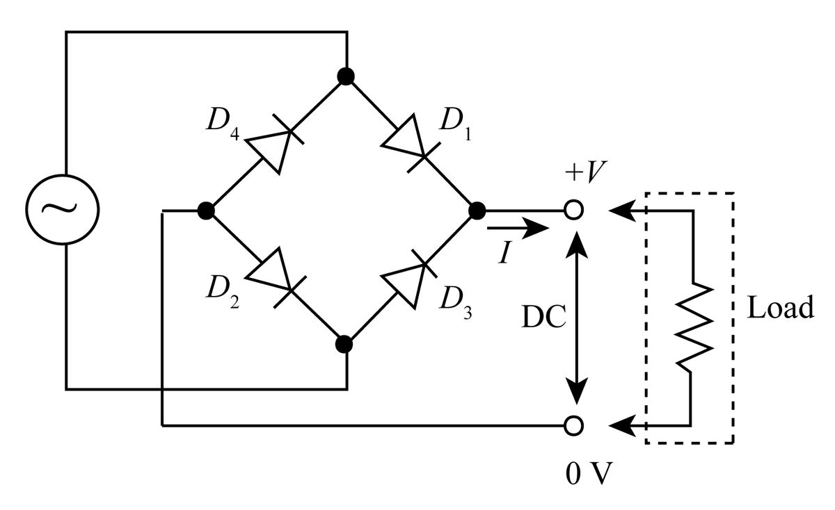
Draw the circuit diagram for a full-wave bridge rectifier with a resistance as the load.


Q: Q5: Design a full-wave rectifier with 1kN load. The rectifier operates from A.C supply of 220v and…
A: The full wave rectifier with the given specifications can be made as: The RMS voltage at the…
Q: Q.2 Consider the full-wave bridge rectifier circuit. The input signal is 120 V (rms) at 60 Hz. The…
A: " Since you have asked multiple questions, we will solve the first question for you. If you want…
Q: Consider the circuit given in Figure (Q4). Let VD = 0.8 V and R = 100 N, find: a) The value of C…
A: Given Diode voltage VD=0.8 V Frequency f=60 Hz Resistance R=100 Ω RMS voltage Vrms=12 V Ripple…
Q: 1-The output waveform we have obtained from the theory above is a pulsating DC waveform. This is…
A: The circuit of half wave rectifier without filter is as shown below : Considering the diode to be…
Q: Write the following for a Semiconverter rectifier with RL load: a) Draw the circuit diagram, supply…
A: There are many devices that work with DC supply, but the supply present is naturally AC. The…
Q: (a) Determine the minimum and maximum input voltages that can maintain the zener diode IN4753A in…
A: To solve above question, one should know about Zener diode and its application. A Zener diode is a…
Q: Explain the operation of the diode in the full-wave bridge rectifier, the zener diode in a voltage…
A: Diode is a unidirectional device. In full wave rectifier, diode convert the negative part of the…
Q: 2.21 What PIV rating is required for the diodes in a bridge rectifier that produces an average…
A: Given: A bridge type rectifier whose average output voltage is 50V. According to question:…
Q: How do you define the output voltage ripple in a rectifier circuit? Suggest a method to reduce the…
A: Rectifiers are used to convert Alternating supply into pulsating DC. It can be controlled as well as…
Q: A full-wave bridge rectifier with a 236.86V p-p sinusoidal input has a load resister of 2KΩ i. Draw…
A: "Since you have posted a question with multiple sub parts we will solve first three subpart for you…
Q: 3- What are the advantages of full wave rectifier comparing to half wave? 4- What is the effect of…
A: Need to explain
Q: Determine the peak output voltage for the bridge rectifier in this figure. Assuming the practical…
A:
Q: 2. A full-wave bridge type rectifier with a 120 Vrms sinusoidal input has a load resistor of 1 kN.…
A: We need to find dc voltage and PIV .
Q: In a fully controlled rectifier with RL load and freewheeling diode. Which of the given condition is…
A: Fully controlled rectifier with RL. Load The period of the free wheeling diode?
Q: Define peak inverse voltage (PIV)? And write its value for Full-wave rectifier?
A: The explanation is as follows.
Q: Given a single phase full wave rectifier shown in figure below, determine Is, Vs, efficiency, RF,…
A:
Q: What is the value of angle of conduction for half and full wave rectifier. Derive expression for it.
A: An device which convert alternating signal in to pulsating direct signal is known as rectifier. The…
Q: Considering a clamper circuit, where capacitance C, load R, the built-in voltage of diode are…
A: clamper circuit is a part of the electronic circuit that is used to change the signal level.
Q: 1. Describe what will happen to the output voltage and PIV of a center-tapped full wave rectifier if…
A: Solution-1) In the centered tapped full-wave rectifier, mainly two diodes are used. This two…
Q: Once the rectifier is designed, it's time to choose the voltage regulator for our source, after all…
A: The given circuit is as shown below,
Q: Sketch VL and IL for the given half-wave rectifier.
A:
Q: Figure shows an AC source G having an effective voltage of 240 V, 60 Hz is connected to a…
A: Let us assume, that a constant current I0 flows through the given RL load. Calculate the dc output…
Q: A full-wave bridge rectifier with a 12V (pk) sinusoidal input has a load resistor of 20 k. (a) If…
A: given that Peak voltage Vm= 12 VRMS Voltage VRMS =122 = 8.48V (a) now…
Q: Q1: Draw the circuit of full wave rectifier mentioned on the circuit all equipment requirements to…
A: In this question we need to draw output voltage signal and need to find output current and voltage.
Q: Write the following for a Semiconverter rectifier with RL load: a) Draw the circuit diagram, supply…
A: Explanation: a) In the semi converter rectifier with RL load we use two diodes and two SCRs. Let Vs…
Q: a steady dc signal. If SCR2 is made open circuit, what will be the average charge current?
A: The single phase full-wave rectifier is a device which convert an AC wave into a pulsing Dc for a…
Q: Draw circuit diagram of a full-wave controlled rectifier and draw the wave shapes of output voltage…
A: The Circuit diagram is shown below. The Wave shape of output voltage is shown below. The Output…
Q: A sinusoidal signal with a maximum value of 12V is applied to the input of the bridge type rectifier…
A: Given Maximum value of sinusoidal signal input to bridge rectifier, Vm = 12V Threshold value of…
Q: When the rms output voltage of a full-wave bridge rectifier is 26.20 V, the peak inverse voltage…
A:
Q: 3. Draw circuit diagram of a half-wave controlled rectifier and draw the wave shapes of output…
A:
Q: A simple voltage regulator is shown in the figure below. The source voltage Vs varies from 8 to 12…
A: Given : Vs= [MIN, MAX]=[8, 12 ] IL=[MIN,MAX]=[50 mA, 150 mA] VL=5 V
Q: Once the rectifier is designed, it's time to choose the voltage regulator for our source, after all…
A: The circuit is as shown below,
Q: WE MEASURED THE CURRENT THAT APPEARED ON THE DRAWN SCREEN AS SHOWN IN THE FIGURE BY USING THREE…
A: The most popular form is the D'Arsonval galvanometer, which uses a light coil of wire strung from a…
Q: A simple diode rectifier has 'ripples' in the output wave which makes it unsuitable as a DC source.…
A:
Q: Show a circuit connection of a half-wave rectifier (together with its output waveform) that can…
A: The negative pulsating DC output can be achieved by inverting the diode connection. So now the diode…
Q: At what point on the input cycle does the PIV occur? For a half-wave rectifier, there is current…
A: In this question we will write answer related to diode problems...
Q: Derive an expression for Idc and Irms of center tap full wave rectifier circuit & find its maximum…
A: Expression for Idc and Irms of center tap full wave rectifier & find its maximum efficiency.…
Q: 5) In the single-phase full wave bridge rectifier circuit with a load of pure resistance, the input…
A: The given circuit diagram is shown below: It is given that: RMS Value of Input Voltage=Vinrms=220…
Q: A simple diode rectifier has 'ripples' in the output wave which makes it unsuitable as a DC source.…
A: Choose the correct option The given statement is true or false?
Q: Draw the circuit of half wave rectifier using operational amplifier and briefly explain it.
A: Operational Amplifier is direct coupled high gain amplifier. The OP-AMP is multi terminal device.…
Q: Determine the ripple factor for the filtered rectifier circuit below when RL= 4KQ. Then explain…
A: Solution : The peak to peak variation of the output of a rectifier is called as ripple factor.…
Q: Design a full wave bridge rectifier power supply to deliver an average voltage of 20 V with a…
A: Given Data: Average output = 20 V Peak to peak ripple voltage = 0.1 V Average load current = 15 mA…
Q: Give a conclusion regarding the experiment of pn junction applications: rectifiers, clippers and…
A: A diode is a two-terminal one-way switch, it will only allow the flow of current in one direction,…
Q: Design rectifier circuits to provide an output of 100 VDc using a) HWR and b) Center-tapped FWR…
A: A rectifier is an AC to DC converter. The rectifier converts AC voltage into pulsating DC Voltage.…
Q: 3. Draw a half wave and full wave rectifier circuit with 1 KQ load resistance and sketch the output…
A: The diodes are made of semiconductor materials. Silicon and germanium are common semiconductors for…
Q: Determine the range of values of Vi that will maintain the Zener diode of Figure.
A: The required parameter of the Zener regulator can be calculated based on the Zener voltage and the…
Q: Draw a half-wave and full-wave rectifier circuit with 1 KQ load resistance and sketch the output…
A: Given Load resistance = 1 kohm Input voltage = 10 sin(wt)
Q: To get a peak output voltage of 40V in a bridge rectifier, What is the approximate rms value of…
A:
Draw the circuit diagram for a full-wave bridge rectifier with a resistance as the load.
the circuit diagram for a full-wave bridge rectifier with a resistance as the load is given below:

Step by step
Solved in 2 steps with 1 images


- S-2) a) On the bridge type full wave rectifier circuit given in the figure Plot the current paths for each of the +/- alternans. b) The waveform of the Vç output voltage is given in the graphs on the side. Draw it in the blank and calculate the peak value and indicate it in the graph. c) Calculate the effective value of the output voltage. (Vç (eff) =… ..?). Note: Diodes are not ideal. VD = 0.7V.Draw the circuit diagram with shape of signal after transformer, after bridge rectifier, with capacitor and with voltage regulator.draw the circuit of a voltage supply comprised of full wave bridge rectifier, capacitor and IC regulator to provide an output of -12V and explain the function of each part.
- Determine the ripple factor for the filtered bridge rectifier with a load as indicated in the figure below.Draw circuit diagram of a half /full-wave single- / three-phase controlled rectifier and draw the wave shapes of output voltage and current for R / R-L load with sinusoidal input.A bridge rectifier circuit has secondary voltage of 12 V Assume secondary resistance and diode forward resistance to be negligible. Load resistance is 100(ohm.) Calculate peak load current, DC load current, rms current and across each diode.
- c) Using a Si diode, design a clamper circuit that will result in the desired output waveform as shown in Figure Q2c. Show overall analysis to justify the proposed design. Vi Vo 20 Designed Clamper Circuit - 3 V -20 - 43 V- Figure Q2cIn the circuit in the figure, an AC voltmeter will be made with full wave rectifier circuit structure. R = 50ohm and diodesResistance values in the direction of transmission are Rd = 100ohm. Inside of the DC ammeter to be used as indicatorthe resistance is very, very small. The AC mark to be measured is Vs = 100 Sinwt Volts.a- Draw the shape of the current passing through the DC Ammeter and calculate its maximum value.b- Find the average value of the current passing through the DC Ammeter.c- Analyze the voltage seen at the ends of diode D1 for both alternans.d- Find the Rms value of the voltage seen at the ends of the diode D1.Draw the circuit diagram of DC power supply of 12 V output by using Full wave rectifier center tap rectifier, filter, Zener diode and any load.
- what is the purpose of installing a filter capacitor in a bridge rectifier circuit? Why don't we install a zener diode which reduces the ripple voltage or to get a consistent voltage wave at Vout?Draw the form of bridge type full wave rectifier power source consisting of 4 layers (lowering, rectifier, filter, regulated) and briefly explain the role of each layer (by drawing the signal entering the layer and the signals coming out of the layer).Derive the average and RMS output voltage for three phase half controlled rectifier with RLE Load or three phase semi converters.