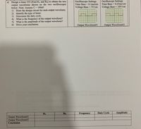
Oscilloscope Settings Time Base = 0.25ms/cm a) Design a timer 555 (Find RA and RB) to obtain the two output waveforms shown on the two oscilloscopes below. Note: Assume C = 100nF. 1) Draw the design circuit for each output waveform. 2) Identify the type of timer. 3) Determine the duty cycle. 4) What is the frequency of the output waveform? 5) What is the amplitude of the output waveform? 6) Drive your conclusion. Oscilloscope Settings Time Base = 0.1ms/cm Voltage Base = 5V/cm Voltage Base = 10V/cm Output Waveform#1 Output Waveform#2 RA RB Frequency Duty Cycle Amplitude Output Waveform#1 Output Waveform#2 Conclusion
Oscilloscope Settings Time Base = 0.25ms/cm a) Design a timer 555 (Find RA and RB) to obtain the two output waveforms shown on the two oscilloscopes below. Note: Assume C = 100nF. 1) Draw the design circuit for each output waveform. 2) Identify the type of timer. 3) Determine the duty cycle. 4) What is the frequency of the output waveform? 5) What is the amplitude of the output waveform? 6) Drive your conclusion. Oscilloscope Settings Time Base = 0.1ms/cm Voltage Base = 5V/cm Voltage Base = 10V/cm Output Waveform#1 Output Waveform#2 RA RB Frequency Duty Cycle Amplitude Output Waveform#1 Output Waveform#2 Conclusion
Oh no! Our experts couldn't answer your question.
Don't worry! We won't leave you hanging. Plus, we're giving you back one question for the inconvenience.
Submit your question and receive a step-by-step explanation from our experts in as fast as 30 minutes.
You have no more questions left.
Message from our expert:
Hi and thanks for your question! Unfortunately we cannot answer this particular question due to its complexity.
We've credited a question back to your account. Apologies for the inconvenience.
Your Question:

Transcribed Image Text:Oscilloscope Settings
Time Base = 0.25ms/cm
a) Design a timer 555 (Find RA and RB) to obtain the two
output waveforms shown on the two oscilloscopes
below. Note: Assume C = 100nF.
1) Draw the design circuit for each output waveform.
2) Identify the type of timer.
3) Determine the duty cycle.
4) What is the frequency of the output waveform?
5) What is the amplitude of the output waveform?
6) Drive your conclusion.
Oscilloscope Settings
Time Base = 0.1ms/cm
Voltage Base = 5V/cm
Voltage Base = 10V/cm
Output Waveform#1
Output Waveform#2
RA
RB
Frequency
Duty Cycle
Amplitude
Output Waveform#1
Output Waveform#2
Conclusion
Recommended textbooks for you

Introductory Circuit Analysis (13th Edition)
Electrical Engineering
ISBN:
9780133923605
Author:
Robert L. Boylestad
Publisher:
PEARSON

Delmar's Standard Textbook Of Electricity
Electrical Engineering
ISBN:
9781337900348
Author:
Stephen L. Herman
Publisher:
Cengage Learning

Programmable Logic Controllers
Electrical Engineering
ISBN:
9780073373843
Author:
Frank D. Petruzella
Publisher:
McGraw-Hill Education

Introductory Circuit Analysis (13th Edition)
Electrical Engineering
ISBN:
9780133923605
Author:
Robert L. Boylestad
Publisher:
PEARSON

Delmar's Standard Textbook Of Electricity
Electrical Engineering
ISBN:
9781337900348
Author:
Stephen L. Herman
Publisher:
Cengage Learning

Programmable Logic Controllers
Electrical Engineering
ISBN:
9780073373843
Author:
Frank D. Petruzella
Publisher:
McGraw-Hill Education

Fundamentals of Electric Circuits
Electrical Engineering
ISBN:
9780078028229
Author:
Charles K Alexander, Matthew Sadiku
Publisher:
McGraw-Hill Education

Electric Circuits. (11th Edition)
Electrical Engineering
ISBN:
9780134746968
Author:
James W. Nilsson, Susan Riedel
Publisher:
PEARSON

Engineering Electromagnetics
Electrical Engineering
ISBN:
9780078028151
Author:
Hayt, William H. (william Hart), Jr, BUCK, John A.
Publisher:
Mcgraw-hill Education,
