Define the following in your own words:1. Positive and negative logic.2. Polarity indicator.3. Dependency notation.4. Active high and active low.5. Dynamic indicator.


Define the following in your own words:
1. Positive and negative logic.
2. Polarity indicator.
3. Dependency notation.
4. Active high and active low.
5. Dynamic indicator.
We are authorized to answer three subparts at a time, since you have not mentioned which part you are looking for, so we are answering the first three subparts, please repost your question separately for the remaining subpart.
1.
POSITIVE AND NEGATIVE LOGIC:
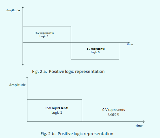
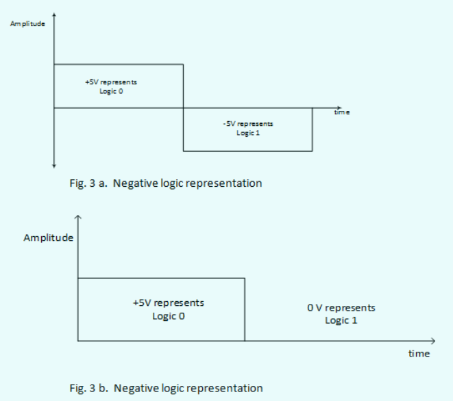
According to the definition of positive logic, a high level of voltage corresponds to logic 1, as well as a low voltage voltage level to logic 0. In the opposite, negative logic, a low voltage voltage level level corresponds to a logic level 1 & a high level of voltage to a logic 0.
The positive logic representation is shown below:
The negative logic representation is shown below:

Step by step
Solved in 4 steps with 3 images


