
Loose Leaf for Engineering Circuit Analysis Format: Loose-leaf
9th Edition
ISBN: 9781259989452
Author: Hayt
Publisher: Mcgraw Hill Publishers
expand_more
expand_more
format_list_bulleted
Videos
Textbook Question
Chapter 10.5, Problem 9P
With reference to the network shown in Fig. 10.19, find the input impedance Zin that would be measured between terminals: (a) a and g; (b) b and g; (c) a and b.
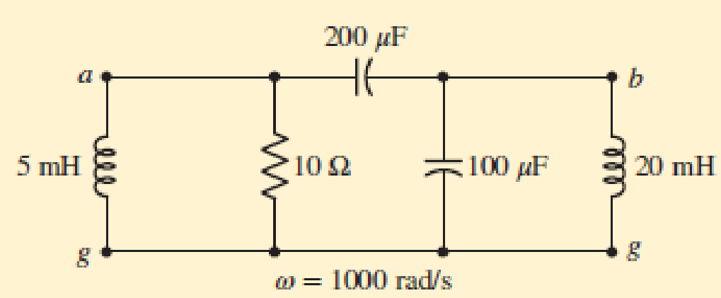
■ FIGURE 10.19
Expert Solution & Answer
Want to see the full answer?
Check out a sample textbook solution
Students have asked these similar questions
10:42
Yo) a ll 92% 2
LTÉ
Sri Sangamesh Goudappanavar started recording
UEE741E-3C_Unit1-Chap2 - PowerPoint
Suresh Jangamshetti
imations
Slide Show
Review
View
Recording
Help
Acrobat
Tell me what you want to do
A A E
O Shape Fill -
P Find
Shape Outline -
Sac Replace
ab
Shapes Arrange Quick
Styles
aby
A -
Shape Effects
E Select
Paragraph
Drawing
Editing
1
1
2..
4
PES
Examples
Estimate cell temperature, open-circuit voltage, and maximum
power output for the KD230GX-LPB module under conditions of 1-
sun insolation and ambient temperature 30°C. The module has a
NOCT of 47°C.
Ans. Cell temperature = 64°C, maximum power = 189.6 W, open circuit
voltage = 31.7 V.
Estimate the cell temperature and power delivered by a 100-W PV module
with the following conditions. Assume 0.5%fC power loss.
a. NOCT = 50°C, ambient temperature of 25°C, insolation of 1-sun.
b. NOCT = 45°C, ambient temperature of 0°C, insolation of 500 W/m².
c. NOCT = 45°C, ambient temperature of 30°C, insolation of 800 W/m².
Ans.…
Using the following sequence definitions,.
2. k0,1.2
Hk) =1. k= 3,4
elsewhere
2. k-0
1. k 1.2
0 elsewhere,
and xik)
a) Plot h(k) and x(k)
evaluate the digital convolution
b) Using the graphical method
c) Applying the convolution formula directly
Click here for image
↑ 11
Rm/
In this circuit, R1 = 502, 11-6 A, 12 = 2 A, Rm = 82./ has units of amperes.
Voc 10.2
112
Determine the Thevenin equivalent circuit at terminals a-b.
Rth = -5.6
State the values of the open-circuit voltage, Voc (in volts), and the equivalent resistance, Rth (in ohms), in the box below. Round your answers to one decimal place.
An example answer is shown below
b
Chapter 10 Solutions
Loose Leaf for Engineering Circuit Analysis Format: Loose-leaf
Ch. 10.1 - Find the angle by which i1 lags v1 if v1 = 120...Ch. 10.2 - Determine values for A, B, C, and if 40 cos(100t ...Ch. 10.2 - Let vs = 40 cos 8000t V in the circuit of Fig....Ch. 10.3 - Prob. 4PCh. 10.3 - If the use of the passive sign convention is...Ch. 10.4 - Let = 2000 rad/s and t = 1 ms. Find the...Ch. 10.4 - Transform each of the following functions of time...Ch. 10.4 - In the circuit of Fig. 10.17, both sources operate...Ch. 10.5 - With reference to the network shown in Fig. 10.19,...Ch. 10.5 - In the frequency-domain circuit of Fig. 10.21,...
Ch. 10.5 - Determine the admittance (in rectangular form) of...Ch. 10.6 - Use nodal analysis on the circuit of Fig. 10.23 to...Ch. 10.6 - Use mesh analysis on the circuit of Fig. 10.25 to...Ch. 10.7 - If superposition is used on the circuit of Fig....Ch. 10.7 - Prob. 15PCh. 10.7 - Determine the current i through the 4 resistor of...Ch. 10.8 - Select some convenient reference value for IC in...Ch. 10 - Evaluate the following: (a) 5 sin (5t 9) at t =...Ch. 10 - (a) Express each of the following as a single...Ch. 10 - Prob. 3ECh. 10 - Prob. 4ECh. 10 - Prob. 5ECh. 10 - Calculate the first three instants in time (t 0)...Ch. 10 - (a) Determine the first two instants in time (t ...Ch. 10 - The concept of Fourier series is a powerful means...Ch. 10 - Household electrical voltages are typically quoted...Ch. 10 - Prob. 10ECh. 10 - Assuming there are no longer any transients...Ch. 10 - Calculate the power dissipated in the 2 resistor...Ch. 10 - Prob. 13ECh. 10 - Prob. 14ECh. 10 - Prob. 15ECh. 10 - Express the following complex numbers in...Ch. 10 - Prob. 17ECh. 10 - Prob. 18ECh. 10 - Evaluate the following, and express your answer in...Ch. 10 - Perform the indicated operations, and express the...Ch. 10 - Insert an appropriate complex source into the...Ch. 10 - For the circuit of Fig. 10.51, if is = 2 cos 5t A,...Ch. 10 - In the circuit depicted in Fig. 10.51, if is is...Ch. 10 - Employ a suitable complex source to determine the...Ch. 10 - Transform each of the following into phasor form:...Ch. 10 - Prob. 26ECh. 10 - Prob. 27ECh. 10 - The following complex voltages are written in a...Ch. 10 - Assuming an operating frequency of 50 Hz, compute...Ch. 10 - Prob. 30ECh. 10 - Prob. 31ECh. 10 - Prob. 32ECh. 10 - Assuming the passive sign convention and an...Ch. 10 - The circuit of Fig. 10.53 is shown represented in...Ch. 10 - (a) Obtain an expression for the equivalent...Ch. 10 - Determine the equivalent impedance of the...Ch. 10 - (a) Obtain an expression for the equivalent...Ch. 10 - Determine the equivalent admittance of the...Ch. 10 - Prob. 40ECh. 10 - Prob. 41ECh. 10 - Find V in Fig. 10.55 if the box contains (a) 3 in...Ch. 10 - Prob. 43ECh. 10 - Prob. 44ECh. 10 - Design a suitable combination of resistors,...Ch. 10 - Design a suitable combination of resistors,...Ch. 10 - For the circuit depicted in Fig. 10.58, (a) redraw...Ch. 10 - For the circuit illustrated in Fig. 10.59, (a)...Ch. 10 - Referring to the circuit of Fig. 10.59, employ...Ch. 10 - In the phasor-domain circuit represented by Fig....Ch. 10 - With regard to the two-mesh phasor-domain circuit...Ch. 10 - Employ phasor analysis techniques to obtain...Ch. 10 - Determine IB in the circuit of Fig. 10.62 if and ....Ch. 10 - Determine V2 in the circuit of Fig. 10.62 if and ....Ch. 10 - Employ phasor analysis to obtain an expression for...Ch. 10 - Determine the current ix in the circuit of Fig....Ch. 10 - Obtain an expression for each of the four...Ch. 10 - Determine the nodal voltages for the circuit of...Ch. 10 - Prob. 59ECh. 10 - Obtain an expression for each of the four mesh...Ch. 10 - Determine the individual contribution each current...Ch. 10 - Determine V1 and V2 in Fig. 10.68 if I1 = 333 mA...Ch. 10 - Prob. 63ECh. 10 - Obtain the Thvenin equivalent seen by the (2 j) ...Ch. 10 - The (2 j) impedance in the circuit of Fig. 10.69...Ch. 10 - With regard to the circuit depicted in Fig. 10.70,...Ch. 10 - Prob. 67ECh. 10 - Determine the individual contribution of each...Ch. 10 - Determine the power dissipated by the 1 resistor...Ch. 10 - The source Is in the circuit of Fig. 10.75 is...Ch. 10 - Prob. 72ECh. 10 - (a) Calculate values for IL, IR, IC, VL, VR, and...Ch. 10 - In the circuit of Fig. 10.77, (a) find values for...Ch. 10 - The voltage source Vs in Fig. 10.78 is chosen such...Ch. 10 - For the circuit shown in Fig. 10.79, (a) draw the...Ch. 10 - For the circuit shown in Fig. 10.80, (a) draw the...Ch. 10 - (a) Replace the inductor in the circuit of Fig....Ch. 10 - Design a purely passive network (containing only...
Knowledge Booster


Learn more about
Need a deep-dive on the concept behind this application? Look no further. Learn more about this topic, electrical-engineering and related others by exploring similar questions and additional content below.Similar questions
- т 2. Consider the circuit is shown in the figure below. The circuit comprises a voltage supply, v(t), resistor (R), inductor (L) and capacitor (C). Let x1 = i and x2 = v. be the state variables for this system, where i and ve are the circuit current and capacitor voltage, respectively. For this system, a) Derive the loop equation, involving integro-differential equations, from first principles b) Write the state differential equations Write the state-space equation in matrix-vector form Sketch the signal-flow graph. c) Show all your work. L v(1)arrow_forward(ACADEMIC) 8205828page%3D1 The equivalent resistance RAR (in the figure) is: A O 62. 10. BO 10. 12. b. not possible to compute without Y to Delta conversion. C. bere to search S3一4arrow_forwardVOLTE ll O ON100% 10:48 + IMG_4550.jpg For the circuit shown, it is required to design a circuit with minimum losses. The value of n (the turns ratio) that maximizes the transferred power to the secondary coil is. (ABET assessment of outcome 2) 4000 2 1:n 120/0°V rms 10 Ω 0.1 O 0.0025 20 400 0.05 None of the above ellarrow_forward
- 10.23. Draw the block diagrams of both the direct forms I and II simulation diagrams for the systems with the following difference equations: (a) 2y[n]y[n 1] + 4y[n-2] = 5x[n] (b) 1 3]arrow_forwardPROBLEM Io.27 For the circuit shown in Figure 10.128, sketch and label vR versus time. Assume that v = K1 for a long time prior to t = 0 as illustrated in the figure. %3D Note that this problem can be solved in a number of simple steps by breaking the problem down into parts and solving each part. There are several ways to do this breakdown, all of roughly equal ease.arrow_forwardConsider the system Transfer Function as shown in Figure 1. Obtain the rise time t, peak time t, maximum overshoot Mp and settling time & when the system is subjected to a unit step input. Given; 3= 0.6 , w = 5 rad/sec E(s) C(3) S(S + 2(w) Figure 1arrow_forward
- Example 10.6. The change of inductance for a moving-iron ammeter is 2µH/degree. The control spring constant is 5 x 10⁷ N-m/degree. The maximum deflection of the pointer is 100°, what is the current corresponding to maximum deflection ? (Measurement & Instrumentation Nagpur Univ. 1993)arrow_forward10.23. Draw the block diagrams of both the direct forms I and II simulation diagrams for the systems with the following difference equations: (d) y[n] 0.25(x[n] + x[n 1] + x[n- 2] + x[n- 3]) .... 00-6arrow_forward1. Consider the translational mechanical network system shown on the figure. A 1-N, f(t), si applied at t=0. If fv=1, find K and M such that the response is characterized by a 4-sec settling time and a 1-sec peak time. Also, what is the resulting %OS? 2. Given the translational mechanical system shown on the figure, where K=1 and f(t) is a unit step, find the values of M and fv to yield a response with 17% overshoot and a settling time of 10 seconds. f. r(1) M Karrow_forward
- 7. (a) For step-down chopper circuit, source voltage Vs = 220 V, chopping period T = 2000' us, on period = 600 µs, load circuit parameters- R=12, L = 5 mH and E =24 V (9 Find whether load current is continuous or not. (ü) Calculate the value of average output current. füi) Compute the maximum and minimum values of steady state output currents.arrow_forwardConsider in the given system = 0.6 and wn = 5 rad/sec. Calculate the rise Time t,,peak time tp, maximum overshoot Mp, and settling time t, (for 2% & 5% criterion) when the system is subjected to a unit-step input. R(s) E(s) w7 s(s+ 25wn) C(s) 40) 0.5 4. Allowable tolerance 0.05 or 0.02arrow_forwardPlease sholve for the i hat, j hat, at k hat. Sample solutions also indicated below.arrow_forward
arrow_back_ios
SEE MORE QUESTIONS
arrow_forward_ios
Recommended textbooks for you
 Delmar's Standard Textbook Of ElectricityElectrical EngineeringISBN:9781337900348Author:Stephen L. HermanPublisher:Cengage Learning
Delmar's Standard Textbook Of Electricity
Electrical Engineering
ISBN:9781337900348
Author:Stephen L. Herman
Publisher:Cengage Learning
Introduction to Two-Port Networks; Author: ALL ABOUT ELECTRONICS;https://www.youtube.com/watch?v=ru2ItcD6unI;License: Standard Youtube License